INDI Library v2.0.7 is Released (01 Apr 2024)
Bi-monthly release with minor bug fixes and improvements
Can anyone share Pictures of a RasPi astro setup
- Hellriegel
-
 Topic Author
- Offline
- Senior Member
-

- Posts: 44
- Thank you received: 10
Replied by Hellriegel on topic Can anyone share Pictures of a RasPi astro setup
Thanks for Your immediate replies and pictures.
I included these in an ad hoc joint presentation about the RasPi aimed at an audience that was not familiar with the differences between the RasPi and an Arduino.
I myself took Your pictures as a suggestion for a better and neat cable placement. (Don't dare to show my cable chaos at my stationary mount.)
")
Please Log in or Create an account to join the conversation.
- Hellriegel
-
Topic Author
- Offline
- Senior Member
-
- Posts: 44
- Thank you received: 10
Replied by Hellriegel on topic Can anyone share Pictures of a RasPi astro setup
thank You for the pictures of Your highly sophisticated setup, especially the compact "OTA module" as I would like to call it. This is almost exactly what we have been discussing at our last "Astro Stammtisch" just 2 weeks ago! (Annotation: The German word "Stammtisch" usually describes a get-together of (exclusively male) participants gossiping about high level politics with mainly low level contributions having at least one beer to many. However, in our case it is more of a meeting of astro nerds in high spirits with more ideas than digestible within a live time.)
We are still debating about some kind of a compact unified power distribution for a mobile setup including 19V (Laptop), 12V, and 5V rails (maybe worth a new topic).
Please Log in or Create an account to join the conversation.
- Rob Lancaster
-

- Offline
- Supernova Explorer
-

- Posts: 2877
- Thank you received: 812
Replied by Rob Lancaster on topic Can anyone share Pictures of a RasPi astro setup
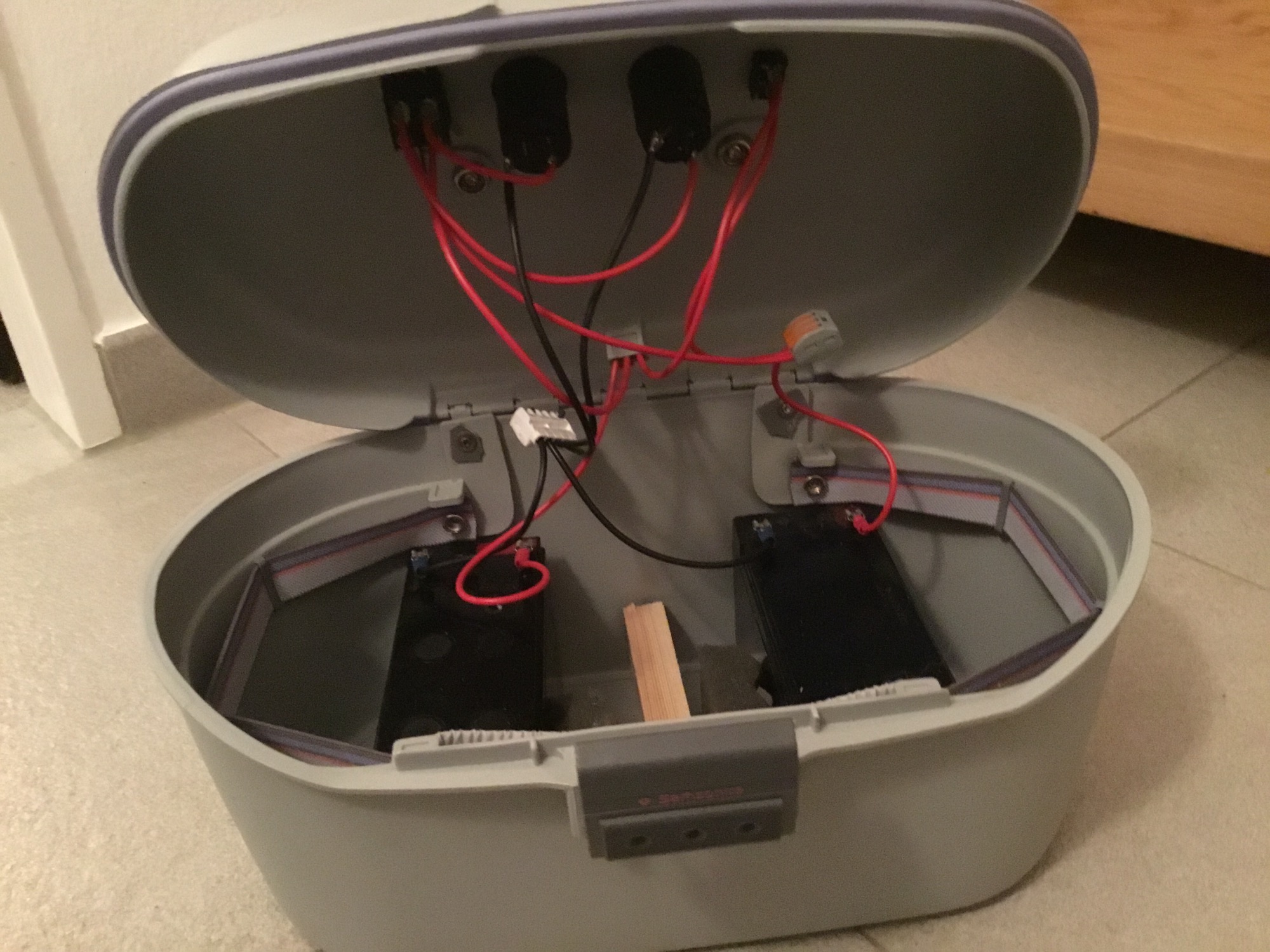
For power distribution, I have a 100 amp hour battery box that I made myself with several cigarette style plugs for equipment. One outlet steps the 12V up to 18V for my mount. Obviously the mount gets plugged into that one. The other plugs are all 12 Volts One goes straight to my SBIG camera A third plug goes to my Dewbuster dew controller, which not only keeps the dew off the guide scope, it also has 12 V power outlets for other equipment. One goes from the Dewbuster to the Moonlite focuser. Another 12 V cord goes from the Dewbuster to my USB hub which accepts 12 volt input. Besides having 7 USB 3 Ports, my hub also has two 5V "power charging" USB plugs, which are really great for powering the Raspberry Pi with a really short USB cord.
Please Log in or Create an account to join the conversation.
- Petar Milevski
-
- Offline
- Premium Member
-

- Posts: 152
- Thank you received: 28
Replied by Petar Milevski on topic Can anyone share Pictures of a RasPi astro setup
Please Log in or Create an account to join the conversation.
Replied by Helge on topic Can anyone share Pictures of a RasPi astro setup
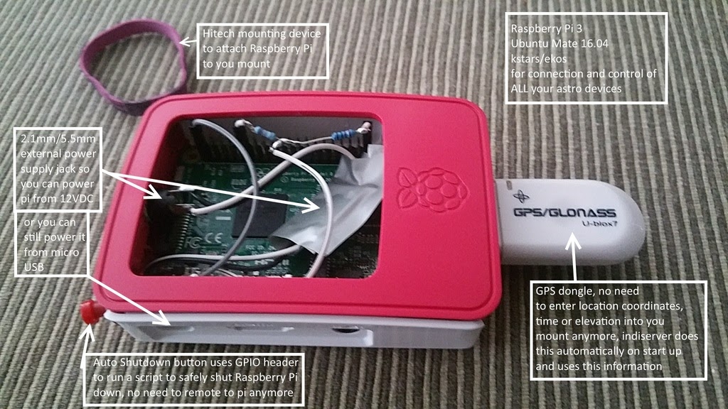
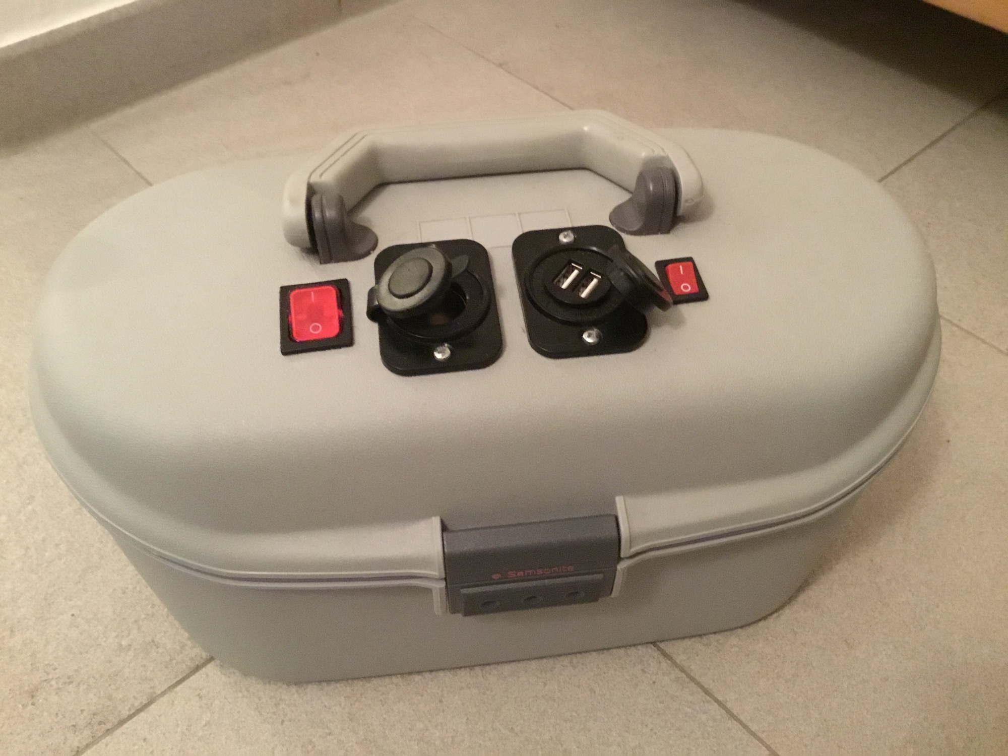
Looks great - how did you connect the wires from the 12v/5v power supply to the micro USB port of the Raspberry? (The micro USB port does not seem to be used?)
Best, Helge
Please Log in or Create an account to join the conversation.
Replied by Helge on topic Can anyone share Pictures of a RasPi astro setup
The left switch is to switch on, the right switch is to combine both batteries (parallel) or keep separate.
Please Log in or Create an account to join the conversation.
- Petar Milevski
-
- Offline
- Premium Member
-
- Posts: 152
- Thank you received: 28
Replied by Petar Milevski on topic Can anyone share Pictures of a RasPi astro setup
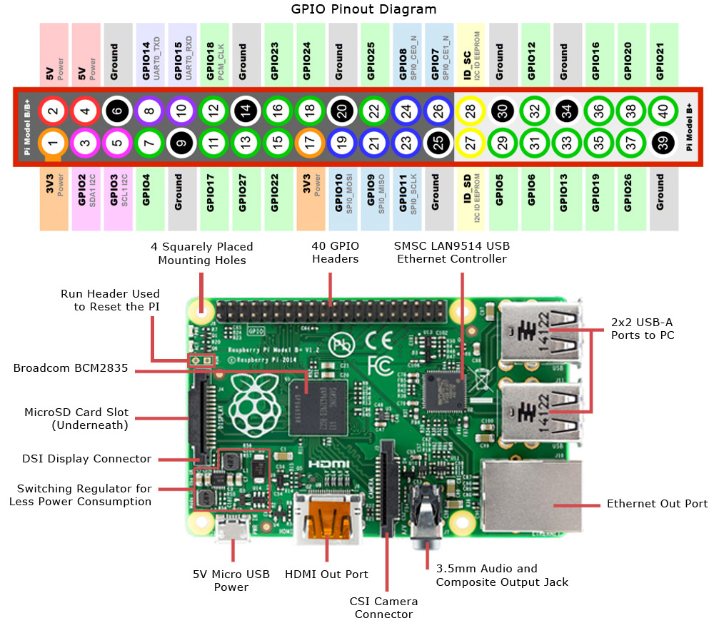
The other way u can do it is via the GPIO. Just find the 5VDC (PIN4) in and a ground (PIN^6) and connect to it. This is how i did my rpi0w. Works unreal. See image for GPIO headers.
regards
Please Log in or Create an account to join the conversation.
- Petar Milevski
-
- Offline
- Premium Member
-
- Posts: 152
- Thank you received: 28
Replied by Petar Milevski on topic Can anyone share Pictures of a RasPi astro setup
Please Log in or Create an account to join the conversation.
Replied by Paul on topic Can anyone share Pictures of a RasPi astro setup
Please Log in or Create an account to join the conversation.
- Graeme Coates
-
- Offline
- New Member
-

- Posts: 3
- Thank you received: 0
Replied by Graeme Coates on topic Can anyone share Pictures of a RasPi astro setup
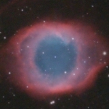
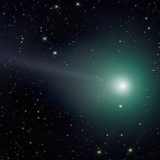
With an 85mm lens I have taken some images lately from here in the UK which you're welcome to use with credits - see:
www.chromosphere.co.uk/2017/12/18/widefi...d-spaghetti-nebulae/
www.chromosphere.co.uk/2017/12/15/belt-sword-loop/
www.chromosphere.co.uk/2017/11/29/widefi...soul-double-cluster/
Please Log in or Create an account to join the conversation.
- Petar Milevski
-
- Offline
- Premium Member
-
- Posts: 152
- Thank you received: 28
Replied by Petar Milevski on topic Can anyone share Pictures of a RasPi astro setup
Please Log in or Create an account to join the conversation.
Replied by Adrian on topic Can anyone share Pictures of a RasPi astro setup
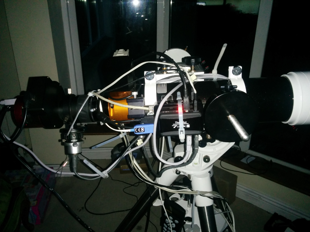
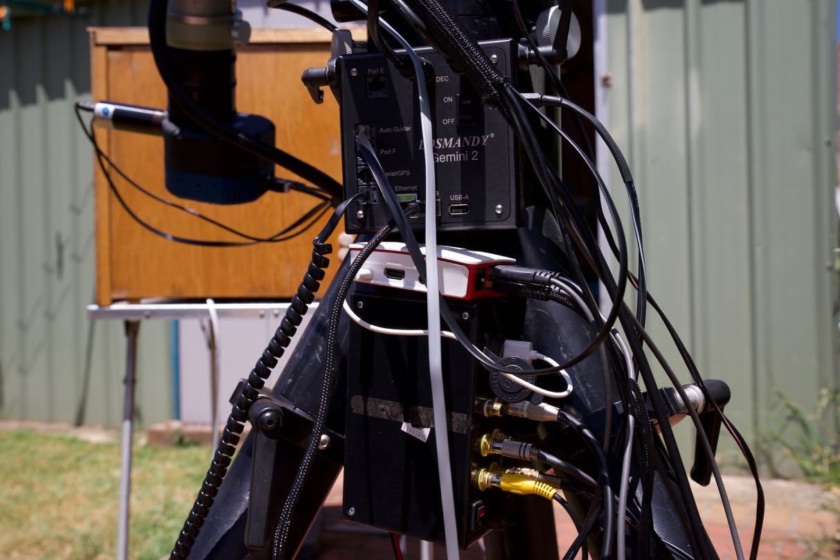
This is set up inside as it is raining outside, again.
The usbhub (PiHut 7 port) is cable tied to the pi ontop of a dovetail bar. (It has an annoying red LED under the cable tie.)
The red object to the left the the main camera, ASI 1600 Mono cooled. There is a built in usb hub which is connected to the EFW. The long light grey USB cable is wrapped around the scope above its attachment to the mount. It is joined by the dark grey USB cable from the QHY guidecamera.
The next black this with the black wire trailing back to the USB hub on the ASI 1600 is the EFW mini.
Next is the OAG with the QHY 5 II mono. (ST4 cable not connected at present)
Nexit is the Flattner Reducer
Next the Moonlite focuser (nice anonised orange)
The scope is and 80mm ED refractor.
Due to the weight of the cameras and focuser, I had to put a counterweight ADM on a dovetail, round thing seen to right on the silver threaded rod.
Note the lack of attention to detail in neatening up the wires.
You could call this the spagetti setup.
Pi and Hub are powered from Voltage regulator
The Voltage regulators are in a weatherproof box hanging off the tripod beside the hand controller. This is fed with 12V.
The large bunch of cables snaking round the tripod include:-
Wired network cable
Two power cords - RPi and Hub
Moonlite focuser serial and USB cables
Mount cable Serial to USB. (White cable with Blue USB connector CE)
If it starts raining when I have set up outside, I throw a big waterproof bag over the lot, like the one used to store backgarden chairs or cover a BBQ.
The USB cables with the serial to USB converted usually like to be connected directly to the RPi.
The USB cable coming from the QHY5-II-M, really likes being plugged into the powered USB hub.
I could not get things working nicely by powering the Pi from the hub. So I connceted it via the micro USB connctor, I cut the other end off and soldered the 5V and ground wires to the Voltage regulator.
Now if the clouds/rain would clear, I could do something more useful.
Please Log in or Create an account to join the conversation.