INDI Library v2.0.7 is Released (01 Apr 2024)
Bi-monthly release with minor bug fixes and improvements
I made this! INDI in an all-in-one power box, with dew heater
Replied by Andrew on topic I made this! INDI in an all-in-one power box, with dew heater
I highly recommend adding GPS to your project to take care of time and location automatically.
www.adafruit.com/product/746
Please Log in or Create an account to join the conversation.

Replied by Noel on topic I made this! INDI in an all-in-one power box, with dew heater
Please Log in or Create an account to join the conversation.
Replied by Noel on topic I made this! INDI in an all-in-one power box, with dew heater
I'd prefer use a module like you suggested; was implementing this straightforward?
Please Log in or Create an account to join the conversation.
Replied by Andrew on topic I made this! INDI in an all-in-one power box, with dew heater
Implementation is fairly straightforward and it allows for attaching an external antenna if necessary. Basic steps include
Wiring to 5V supply
Cross wiring TX and RX to GPIO Pins on the Pi. [Tx to Rx, Rx to Tx]. Page 11 of Documentation
Configure boot/config.txt. Line 1 will enable the MiniUART , and lock to core frequency to 250, disabling turbo because Mini UART and CPU Core frequency are relative. Line 2 defines the pin connected to PPS, example here is pin 4.
enable_uart=1
dtoverlay=pps-gpio,gpiopin=4
Configure /etc/default/gpsd to collect
DEVICES="/dev/ttyS0"Finally configure NTP to use time from GPS
/etc/ntp.conf
# Read the rough GPS time from device 127.127.28.0
# Read the accurate PPS time from device 127.127.28.1

server 127.127.28.0 minpoll 4 maxpoll 4
fudge 127.127.28.0 time1 0.535 refid GPS
server 127.127.28.1 minpoll 4 maxpoll 4 prefer
fudge 127.127.28.1 refid PPSPlease Log in or Create an account to join the conversation.
Replied by Andrew on topic I made this! INDI in an all-in-one power box, with dew heater
Please Log in or Create an account to join the conversation.
- Vincent Groenewold
-

- Offline
- Elite Member
-

- Posts: 365
- Thank you received: 32
Replied by Vincent Groenewold on topic I made this! INDI in an all-in-one power box, with dew heater
")
Please Log in or Create an account to join the conversation.
Replied by Noel on topic I made this! INDI in an all-in-one power box, with dew heater
I've started brainstorming 'Mk 2' and will power any fans from a dedicated 5v or 3.3v line - or at least a module that can handle the current with ease.
Please Log in or Create an account to join the conversation.
Replied by Noel on topic I made this! INDI in an all-in-one power box, with dew heater
Please Log in or Create an account to join the conversation.
- Vincent Groenewold
-
- Offline
- Elite Member
-
- Posts: 365
- Thank you received: 32
Replied by Vincent Groenewold on topic I made this! INDI in an all-in-one power box, with dew heater
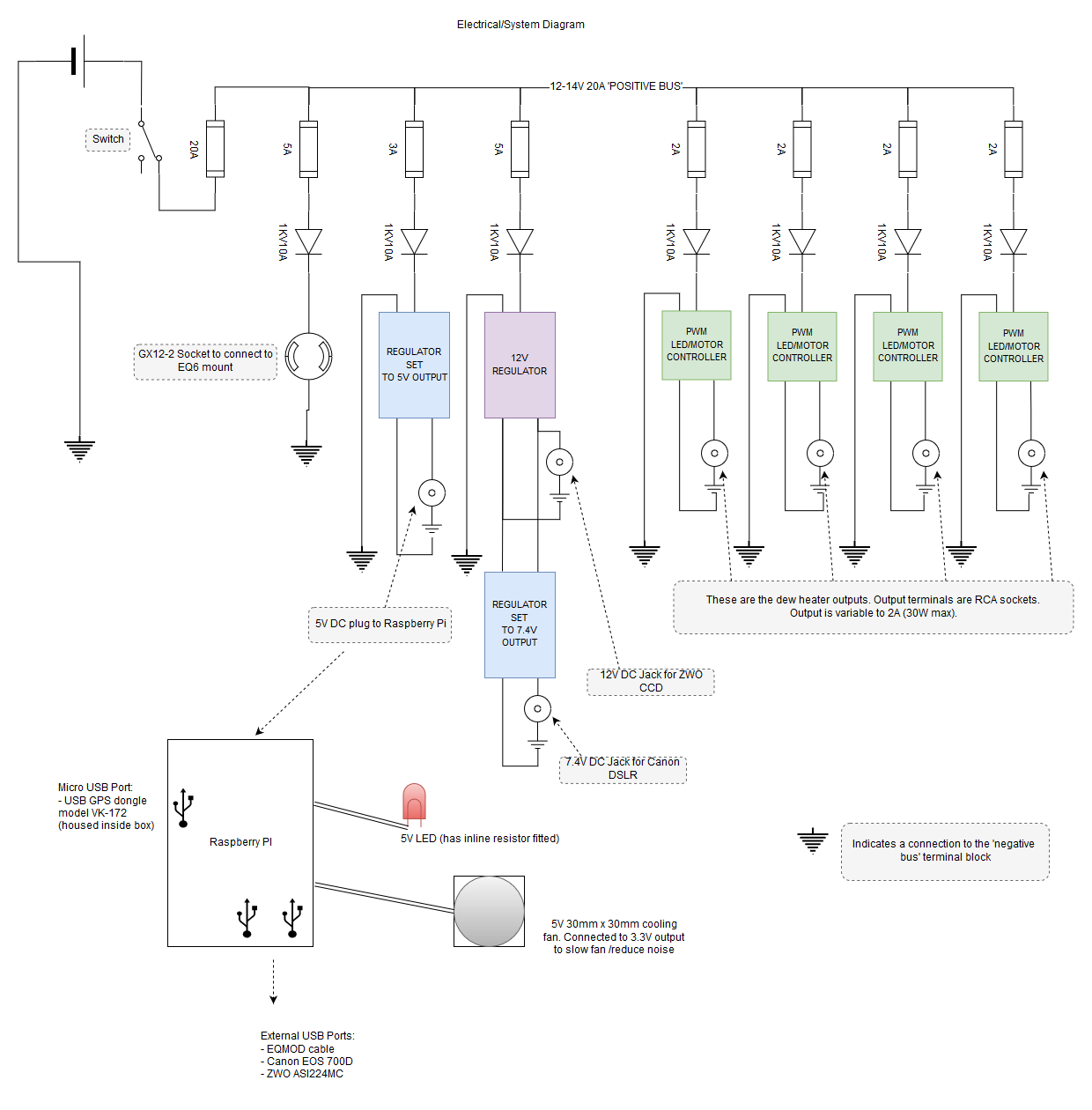
I'm a beginner in electronics, but have learned quite a bit about the various components in the past year. I also learned how to solder and read the diagrams. What I always end up finding difficult, is how to properly connect everything to ground. Is it simply, in your case, that all components feed back to the negative wire of the mains? Please Log in or Create an account to join the conversation.
Replied by Noel on topic I made this! INDI in an all-in-one power box, with dew heater
This bus bar needs to support the maximum current load of all modules combined so give that some consideration when selecting the part. You could make your own if you have the tools and materials as some bigger modules get quite expensive.
For my project I summed the maximum rated load of all components and then rounded up - in reality it's been overkill, while running my system draws about a quarter of what it's 'designed' to do - but I feel better safe than sorry.
Please Log in or Create an account to join the conversation.
- Simon Dodd
-

- Offline
- New Member
-

- Posts: 18
- Thank you received: 0
Replied by Simon Dodd on topic I made this! INDI in an all-in-one power box, with dew heater
Thanks for sharing! Please Log in or Create an account to join the conversation.
Replied by Noel on topic I made this! INDI in an all-in-one power box, with dew heater
Some lessons I've learnt and improvements I'm considering:
Move to an arduino dew heater controller, this should be less bulky in the case as using the stripped down LED controllers made things a bit bulky.
The fuse panel module added a lot of bulk to the unit. First appearances make it look a bit snazzy like a RigRunner but really would have been much better if built onto a PCB - or ommited and had a 1 or 2 fuses where it really counts. My next version will be far less busy looking.
Getting a PCB made is pretty cheap these days - many online services are available, even if you end up with 3-5 of the same board it's still cheap. I'm planning to put much of the 'power distribution' side of things to PCB to cut back on the mess of internal wiring. If it wasn't for the wiring and fuse panel the whole unit would be much smaller and lighter.
I now have a 3D printer as well so have a lot more options when it comes to the case design to put it in. I intend to 3D print an inner skeleton which will be sandwiched between two thin aluminium plates. The skeleton will hold the boards and connectors, the aluminium panels will be tough for mounting between rings and dovetails (with plenty of plastic around each through-hole internally).
(I stole some ideas from QHY - have a look at the internals of the QHY Astrobar here: )
Finally, a small blower fan like those used in laptops will allow for a slimmer design.
Have fun!
Please Log in or Create an account to join the conversation.