


Hi Jasem,
Can you kick a build to the launchpad for the latest libatik & indi-atik?
With the latest SDK (2023.07.14) appears there're few issues fixed (include some old 4xx models having the horizontal lines)
Thank you!
Stephen
Read More...
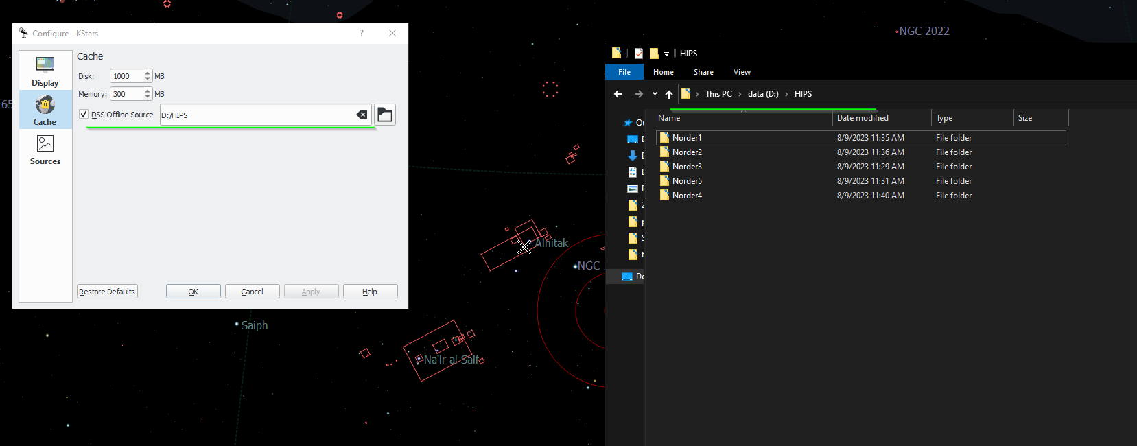
I just figured it out - it has to be under the equivalent of kstars /usr directory, so putting the offline files in this folder in Windows works fine:
C:\Users\<user name>\AppData\Local\kstars\HIPS
Read More...
Dear all
Any one try to install the offline files to Windows folder?
I tried, and pointed the directory to the parent folder in Windows that contains the Norder1, Norder2, etc. But it does not work. See attached screen.
Read More...
To supplement I tried running gdb --ex run --eval-command="set follow-fork-mode child" --args indiserver -v indi_atik_ccd
But gdb did not catch the catch the crash and break. It just simply let the driver try 10 times..... see below
pi@raspberrypi:~ $ gdb --ex run --eval-command="set follow-fork-mode child" --args indiserver -v indi_atik_ccd
GNU gdb (Raspbian 8.2.1-2) 8.2.1
Copyright (C) 2018 Free Software Foundation, Inc.
License GPLv3+: GNU GPL version 3 or later <gnu.org/licenses/gpl.html>
This is free software: you are free to change and redistribute it.
There is NO WARRANTY, to the extent permitted by law.
Type "show copying" and "show warranty" for details.
This GDB was configured as "arm-linux-gnueabihf".
Type "show configuration" for configuration details.
For bug reporting instructions, please see:
<www.gnu.org/software/gdb/bugs/>.
Find the GDB manual and other documentation resources online at:
<www.gnu.org/software/gdb/documentation/>.
For help, type "help".
Type "apropos word" to search for commands related to "word"...
Reading symbols from indiserver...done.
Starting program: /usr/bin/indiserver -v indi_atik_ccd
[Thread debugging using libthread_db enabled]
Using host libthread_db library "/lib/arm-linux-gnueabihf/libthread_db.so.1".
2022-03-10T15:03:12: startup: /usr/bin/indiserver -v indi_atik_ccd
[Detaching after fork from child process 748]
2022-03-10T15:03:12: Driver indi_atik_ccd: pid=748 rfd=3 wfd=6 efd=7
2022-03-10T15:03:12: listening to port 7624 on fd 4
2022-03-10T15:03:12: Driver indi_atik_ccd: stderr EOF
2022-03-10T15:03:12: Driver indi_atik_ccd: restart #1
[Detaching after fork from child process 749]
Child process 748 died
2022-03-10T15:03:12: Driver indi_atik_ccd: pid=749 rfd=0 wfd=6 efd=7
2022-03-10T15:03:13: Driver indi_atik_ccd: stderr EOF
2022-03-10T15:03:13: Driver indi_atik_ccd: restart #2
[Detaching after fork from child process 750]
Child process 749 died
2022-03-10T15:03:13: Driver indi_atik_ccd: pid=750 rfd=0 wfd=6 efd=7
2022-03-10T15:03:13: Driver indi_atik_ccd: stderr EOF
2022-03-10T15:03:13: Driver indi_atik_ccd: restart #3
[Detaching after fork from child process 751]
Child process 750 died
2022-03-10T15:03:13: Driver indi_atik_ccd: pid=751 rfd=0 wfd=6 efd=7
2022-03-10T15:03:13: Driver indi_atik_ccd: stderr EOF
2022-03-10T15:03:13: Driver indi_atik_ccd: restart #4
[Detaching after fork from child process 752]
Child process 751 died
2022-03-10T15:03:13: Driver indi_atik_ccd: pid=752 rfd=0 wfd=6 efd=7
2022-03-10T15:03:13: Driver indi_atik_ccd: stderr EOF
2022-03-10T15:03:13: Driver indi_atik_ccd: restart #5
[Detaching after fork from child process 753]
Child process 752 died
2022-03-10T15:03:13: Driver indi_atik_ccd: pid=753 rfd=0 wfd=6 efd=7
2022-03-10T15:03:14: Driver indi_atik_ccd: stderr EOF
2022-03-10T15:03:14: Driver indi_atik_ccd: restart #6
[Detaching after fork from child process 754]
Child process 753 died
2022-03-10T15:03:14: Driver indi_atik_ccd: pid=754 rfd=0 wfd=6 efd=7
2022-03-10T15:03:14: Driver indi_atik_ccd: stderr EOF
2022-03-10T15:03:14: Driver indi_atik_ccd: restart #7
[Detaching after fork from child process 755]
Child process 754 died
2022-03-10T15:03:14: Driver indi_atik_ccd: pid=755 rfd=0 wfd=6 efd=7
2022-03-10T15:03:14: Driver indi_atik_ccd: stderr EOF
2022-03-10T15:03:14: Driver indi_atik_ccd: restart #8
[Detaching after fork from child process 756]
Child process 755 died
2022-03-10T15:03:14: Driver indi_atik_ccd: pid=756 rfd=0 wfd=6 efd=7
2022-03-10T15:03:14: Driver indi_atik_ccd: stderr EOF
2022-03-10T15:03:14: Driver indi_atik_ccd: restart #9
[Detaching after fork from child process 757]
Child process 756 died
2022-03-10T15:03:15: Driver indi_atik_ccd: pid=757 rfd=0 wfd=6 efd=7
2022-03-10T15:03:15: Driver indi_atik_ccd: stderr EOF
2022-03-10T15:03:15: Driver indi_atik_ccd: restart #10
[Detaching after fork from child process 758]
Child process 757 died
2022-03-10T15:03:15: Driver indi_atik_ccd: pid=758 rfd=0 wfd=6 efd=7
2022-03-10T15:03:15: Driver indi_atik_ccd: stderr EOF
2022-03-10T15:03:15: Driver indi_atik_ccd: Terminated after #10 restarts.
2022-03-10T15:03:15: good bye
[Inferior 1 (process 745) exited with code 01]
Read More...
Hi everyone,
I'm trying to get my pi zero W runs as an indi server. When I start the indi_atik_ccd the driver keeps crashing.
I tried to run indiserver -vvv but the log did not print much.
Recompile indiserver & the atik driver in the pi zero, but that did not resolve the problem.
Any ideas to have indiserver print out more debug log in command line mode?
2022-03-10T03:12:39: Driver indi_atik_ccd: restart #9
2022-03-10T03:12:39: Driver indi_atik_ccd: pid=544 rfd=5 wfd=11 efd=12
Child process 543 died
2022-03-10T03:12:39: Driver indi_atik_ccd: stderr EOF
2022-03-10T03:12:39: Driver indi_atik_ccd: restart #10
2022-03-10T03:12:39: Driver indi_atik_ccd: pid=545 rfd=5 wfd=11 efd=12
Child process 544 died
2022-03-10T03:12:39: Driver indi_atik_ccd: stderr EOF
2022-03-10T03:12:39: Driver indi_atik_ccd: Terminated after #10 restarts.
Child process 545 died
Read More...

Hi Chris,
I fixed the issue at the serial number and made a pull request.
And Jasem is asking for the documentation I will prepare one and upload later, okay?
Stephen
Read More...
Hi
Not sure if this is in wishlist - is it possible to set the Main Camera ROI from FITS viewer?
Like using the mouse to draw a rectangle and then say "Set this ROI" and update the main camera X, Y, W, H settings.
Reason I need this is that I am planning to image with an SCT, and would like to adjust the SCT collimation with a Duncan mask - where a star will become a 3 arcs when it comes to near focus. My camera is an Atik 490ex - which is sort of slow in USB2 transfer in full resolution. So I'll be needing the ROI for speeding up the transfer. I can set the ROI manually by observing the area I need with the viewer plus the grid display. Just want to see if there's a more handy way to set it "visually" where I can select a region from the FITS viewer, and turn it into the ROI.
Thanks & clear skies
Stephen
Read More...
Christopher,
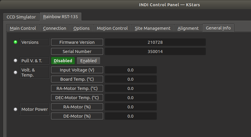
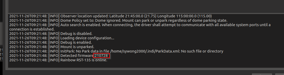
Yes I checked the printlog at the bottom also and I can see the correct firmware version. So may be just a field problem on the upper textbox.
Read More...

Christopher, it's ok, no worries ")
and mine firmware/serial looks like this.
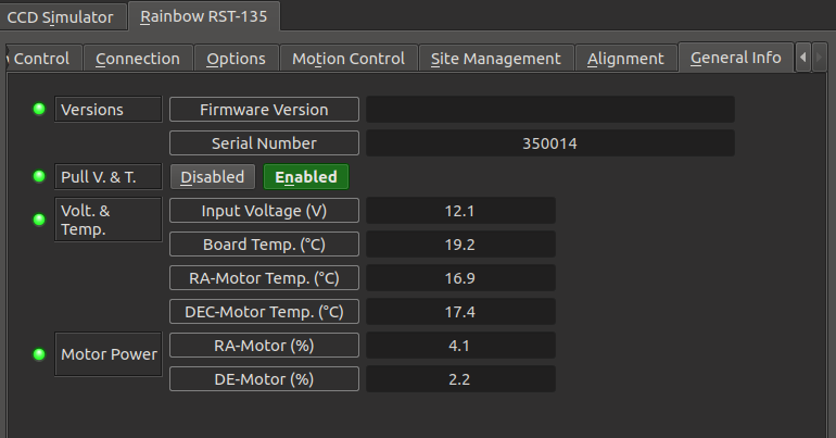
I will have to find out why the firmware version is not appearing.
Read More...
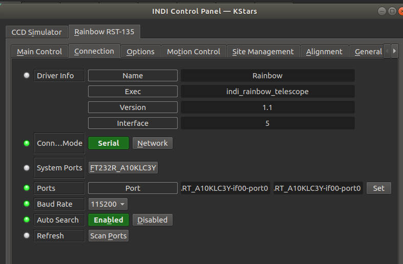
Mine looks like this.... appears to be normal.
Willem can you try at the Options Tab, and Purge Configuration once, and restart INDI and see if the port comes back?
Read More...
I've checked the command works well. But I would recommended connecting the hand controller - when a star is aligned, there'll be a beep sound from the iHubo and you can see the number of stars aligned from the HC display. At first I thought the HC is kind of bulky, but later I've found it's handy on certain commands. Like I want to HOME the mount I just press and hold ILL.
Read More...