


Hi Folks,
I hope this promising project is still growing ! I'm very impatient to see the final version.
Clear Skies
Franck
Read More...
I meant new astrophoto session, so yes the box was powered off and restarted. Maybe I messed up with the viewer (closed it and was not able to reopen it) the first time, this is the only explanation I have.
Read More...
Hi folks
Merry Christmas !
Trying to use solving functionnality, but when I click "Capture and Solve" the solver get stuck at Catpruing Image ? I checked I was able to capture images with my camera (ASI1600mm pro) and it works fine. I selected the same camera in the Aling tab but it seems not able to connect to the camera to get a picture ?
Any idea ?
Read More...
Hi there !
So using usb is fine, but I'm not able to have the BT working on my Asus Tinker board running armbian. It seems that RFCOMM is not available. I tryed to build a new kernel with the proper options, but it seems building a new kernel is not so straightforward ![]()
So I think It will stick to the usb version.
Read More...
Hi,
So I made some progress. The tic and HC-05 are connected. HC-05 is well connected to the Tinker Board, but I can no manage to have RFCOMM TTY working. It seems not to be avaialble with my kernel. I created a new post on Armbian forum to get help, so stay tuned.
Read More...

Hi Helge, It's been a long time ![]() - I eventually found an opportunity to use a pololul tic and your code to run a focuser on a new setup. The Tic software is now installed on my Tinker Board, and I'm waiting for a Pololu tic t825. I'll keep you updated with my progress.
- I eventually found an opportunity to use a pololul tic and your code to run a focuser on a new setup. The Tic software is now installed on my Tinker Board, and I'm waiting for a Pololu tic t825. I'll keep you updated with my progress.
Clear Skies
Franck
Read More...


According to the G7020-KT datasheet (
innovictor.com/pdf/UBX-G7020-Kx_DataShee...01)_Confidential.pdf
section 6.1.1) , pin 8 is for usb_DM (D-) and pin 10 is for usb DP (D+).
According to the usb connector design central pin 2 is for D- and pin 3 is for D+, pin 1 is for vcc and pin 4 is for gnd
So if I not wrong this shoudl be something like this :
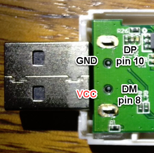
Please double check vcc and ground before plugin !!
Read More...