- 1. Summary
- 2. Short on configuring the Arduino IDE
- 3. Soddering and connecting the sensors
- 4. Configuring, compiling, uploading and debuuging meteoTEST
- 5. Configuring, compiling and uploading induinoMETEO
- 6. Connecting induinoMeteo to KStars with indi_duino driver
- 7. Connecting meteostationWEB to induinoMETEO, and serving trough Apache
- 8. Printing and assembling the MeteoStation printable hardware
- 9. Links to sensors, printable hardware and resources
1. Summary
The induino MeteoStation is a complete weather station with arduino firmware, indilib driver and a webinterface with current status and graphs that range back in time from 3 hours to one month.
The indilib driver is capable of issuing alerts, like daytime, clouded, frezzing and more. Indi clients will react to alerts and can be configured to close your observatory and stop the imaging session in unsafe conditions.
MeteoStation does not have a wind or rain sensor, but can be used in combination with wunderground weather trough Meta weather for an extended weather service. There is also seldom rain without the detection of clouds.
This howto will show you how to setup and build the induino meteostation.
I will use the Adafruit Trinket Pro 5v, but other compatible arduinos could be used.
Keep in mind that the SDA and SDL ports are used for the Ir and pressure sensor. Digital pin 3 is used for the humidity sensor and analog 0 for the ir radiance sensor.
For the Trinket pro we will also use ground, 5v, RX and TX of the FTDI header, as the Trinket does not support serial console over the USB port.
Meteostation can be used as a ‘standalone’ weather station for any none observatory use. This could be a raspberry pi or almost any other linux box running apache with indilib installed locally.
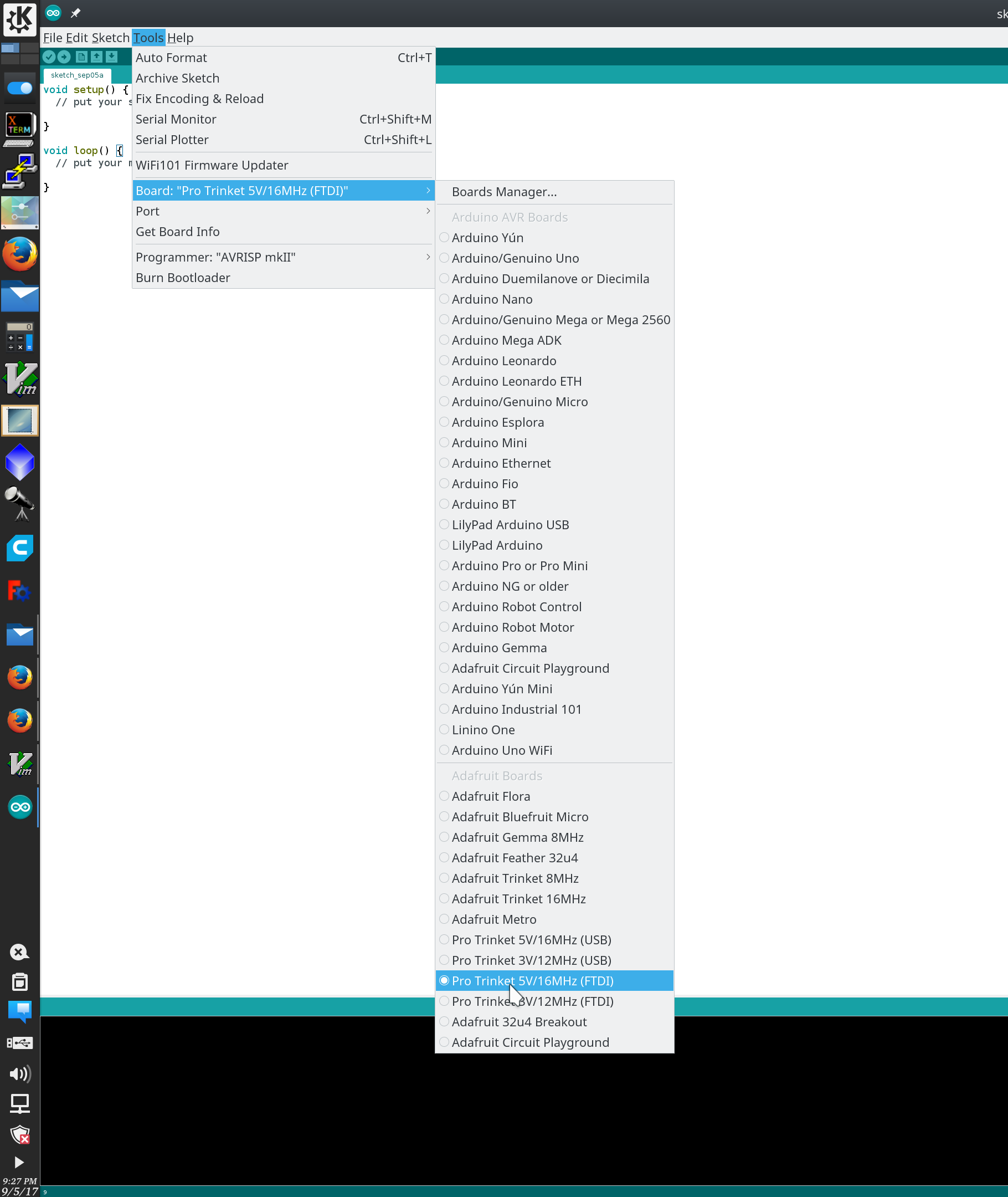
2. Short on configuring the Arduino IDE
First you must set up the Arduino IDE with the Adafruit Pro Trinket board configuration.
Follow the steps on Adafruit’s web page to add the boards.
See Adafruit’s IDE Setup for ‘Additional Boards Manager URL’
If you are using a FTDI cable with no software reset, you can skip adding the port.
When you want to upload the firmware, start off by compiling the sceatch [Ctrl + R] then connect the USB to FTDI dongle to your pc and hit [Ctrl + U] to upload.
The IDE will autoselect the /dev/ttyUSBX port.
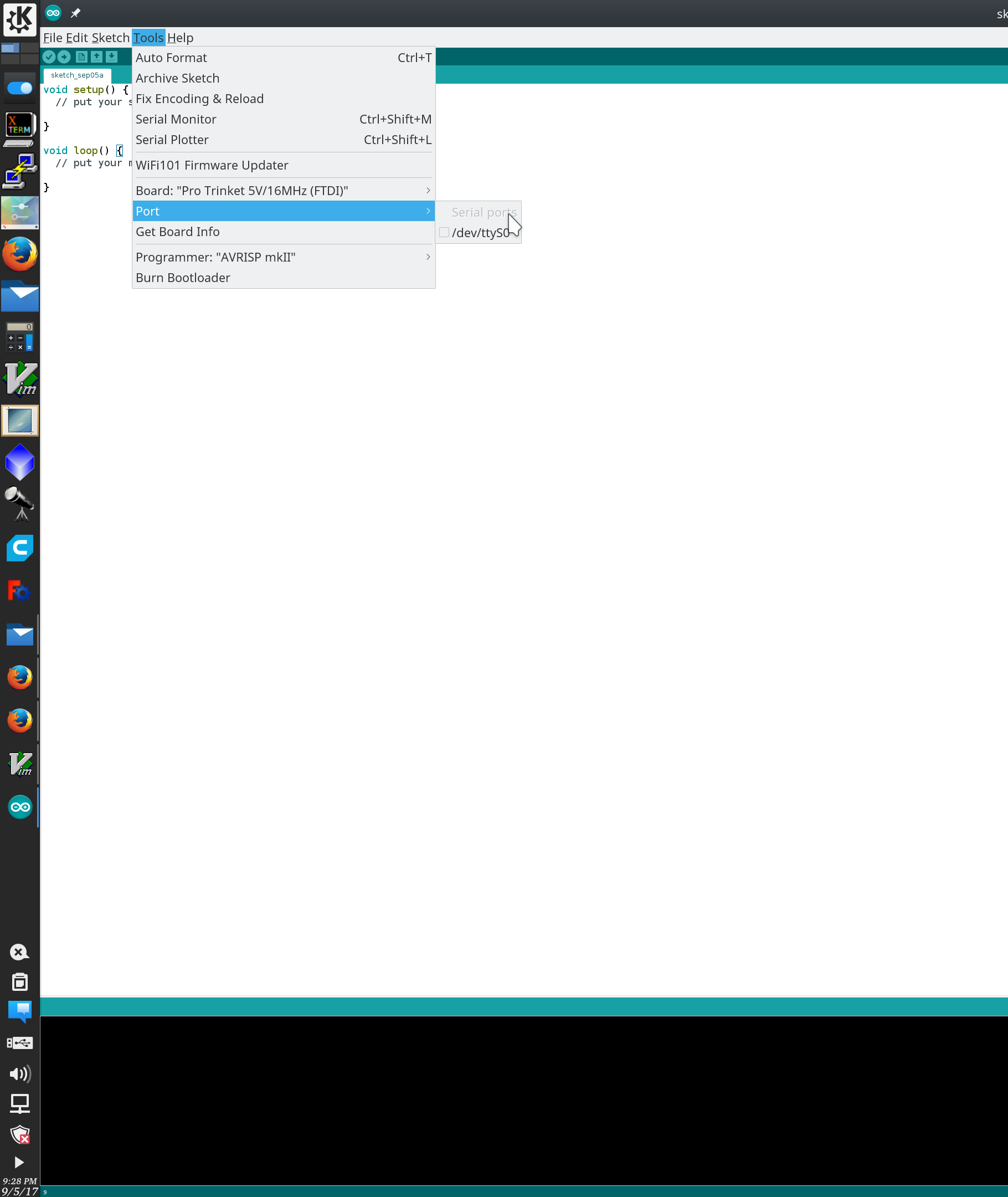
If the autodetect fails, then connect the dongle, select port and short out the ground and reset pin on the FTDI header. This will reset / reboot the arduino and put it in upload mode.
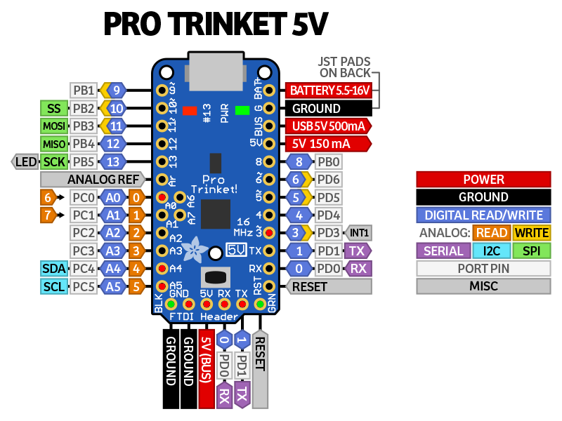
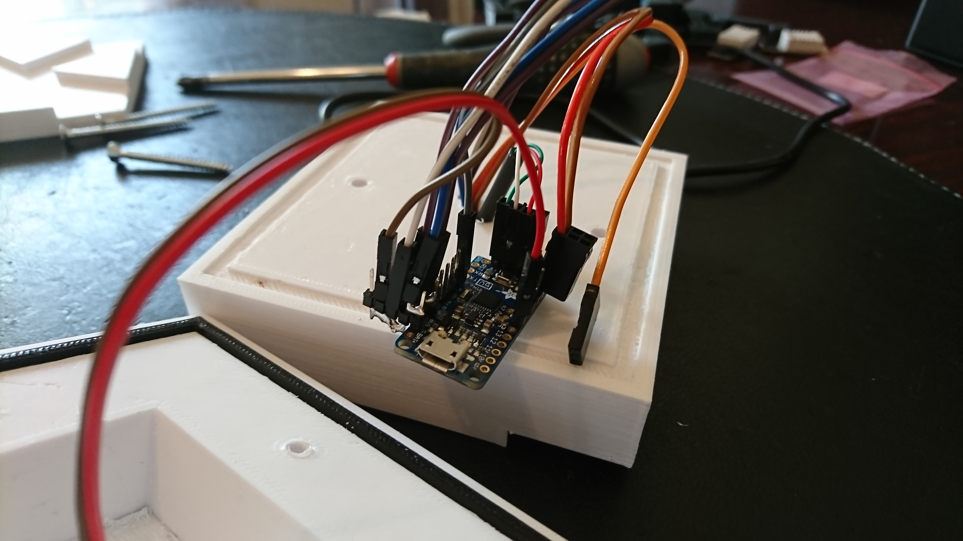
3. Soddering and connecting the sensors
The pins being used is marked out with red centers.
- A0 (Analog 0) is IR Radiance input
- SDA and SCL (A4 and A5) is used for MLX90614 (IR) sensor and BMP 180 (pressure) sensor
- 3 (Digital 3) is used for the DHT22 (humidity) sensor
- The FTDI header is used for serial to USB connection
The pins with green centers are the FTDI reset pins. This will reboot board and put it in upload mode.
If you are building this device with the hardware used in this tutorial, you will not need to change any pinnnumbers in the firmware. For links to the hardware being used, see the last section of this tutorial.
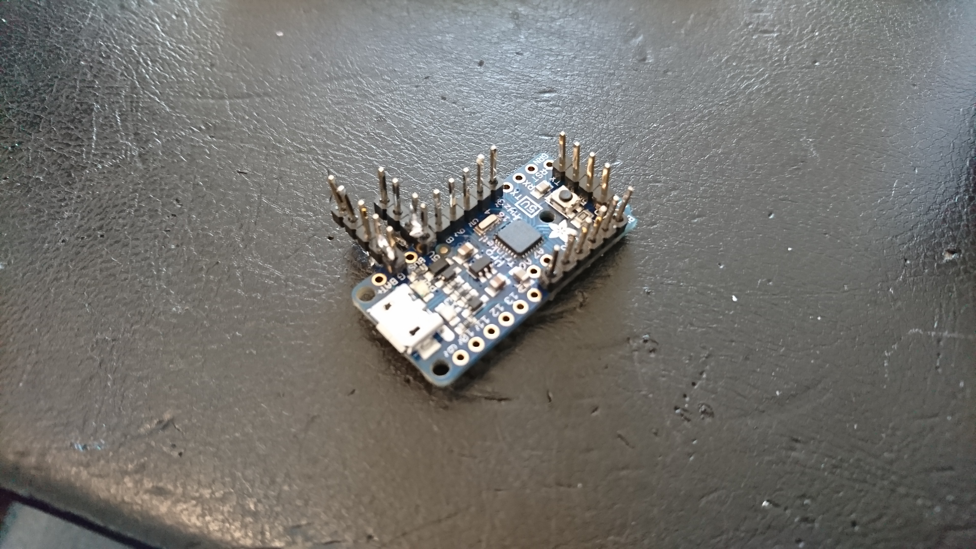
When setting up for the first time I woud ideally just sodder the pins on the underside of the arduino, place it on a breakout board and have easy access to test the sensors. I ended up by soddering on some of the pins and using wires with connectors. Before completing the build I did have to remove the pins I added for gnd and +5v and sodder the wires, as it was using to mutch space.
4. Configuring, compiling, uploading and debuuging meteoTEST
Start out by not changing anything in the firmware, compile and upload, then open the Serial Monitor [Ctrl + Shift + M]
If you see a output like this, the you are good to go. Double check that the sensor values change when you subjet them to temperature, light and humidity changes.
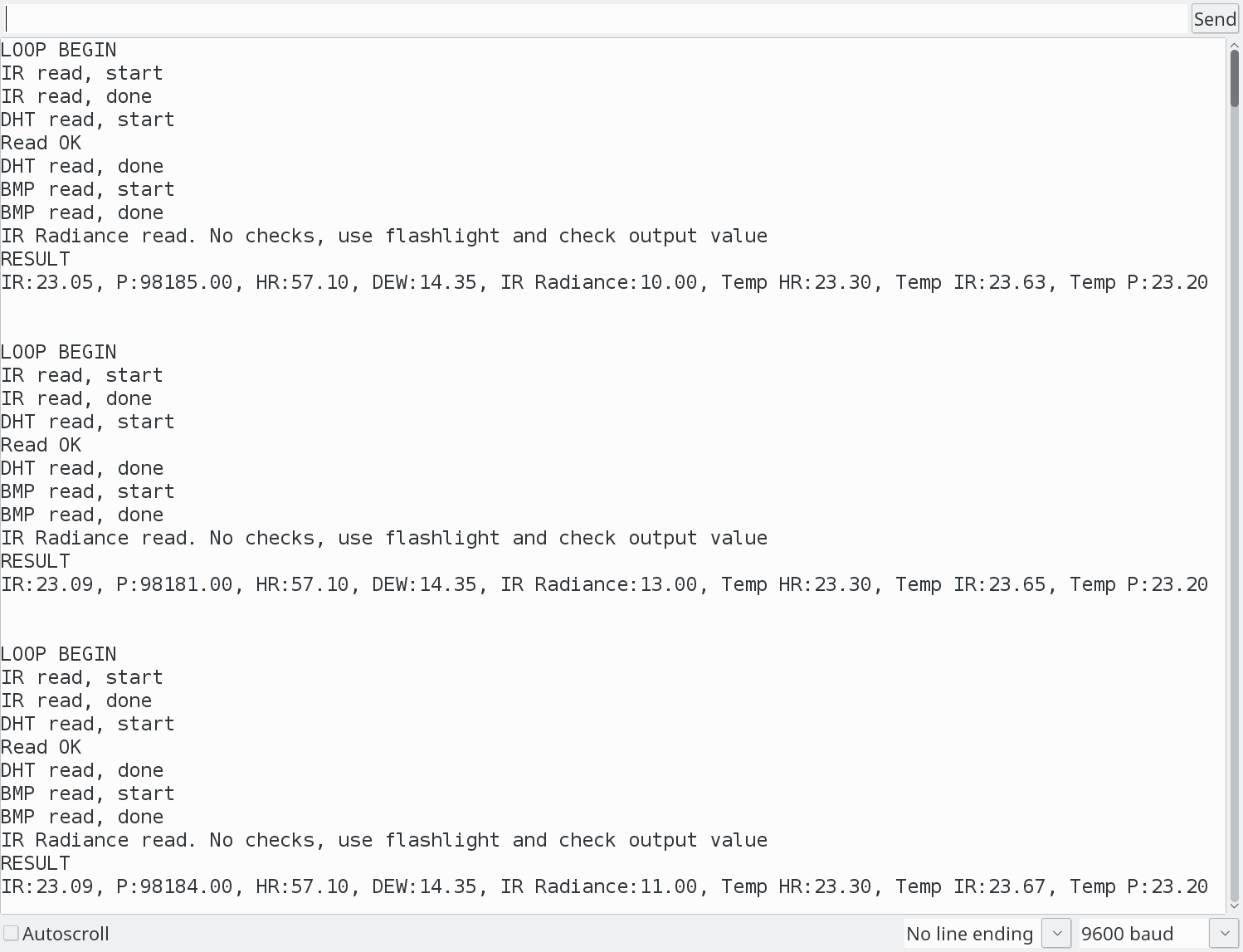
If you see no output at all, then the firmware might have crashed before you connected the serial monitor.
To verify that you have compiled and uploaded the firmware correctly, then comment out all the #define USE_*_Sensor and upload again. If you see a output in the monitor with (X sensor skipped, not defined, ending with a RESULT with all 0 values), then you can start adding the sensors back, until you see witch fails.
When the failing sensor is located, then it’s just a matter of checking wiring and pinouts.
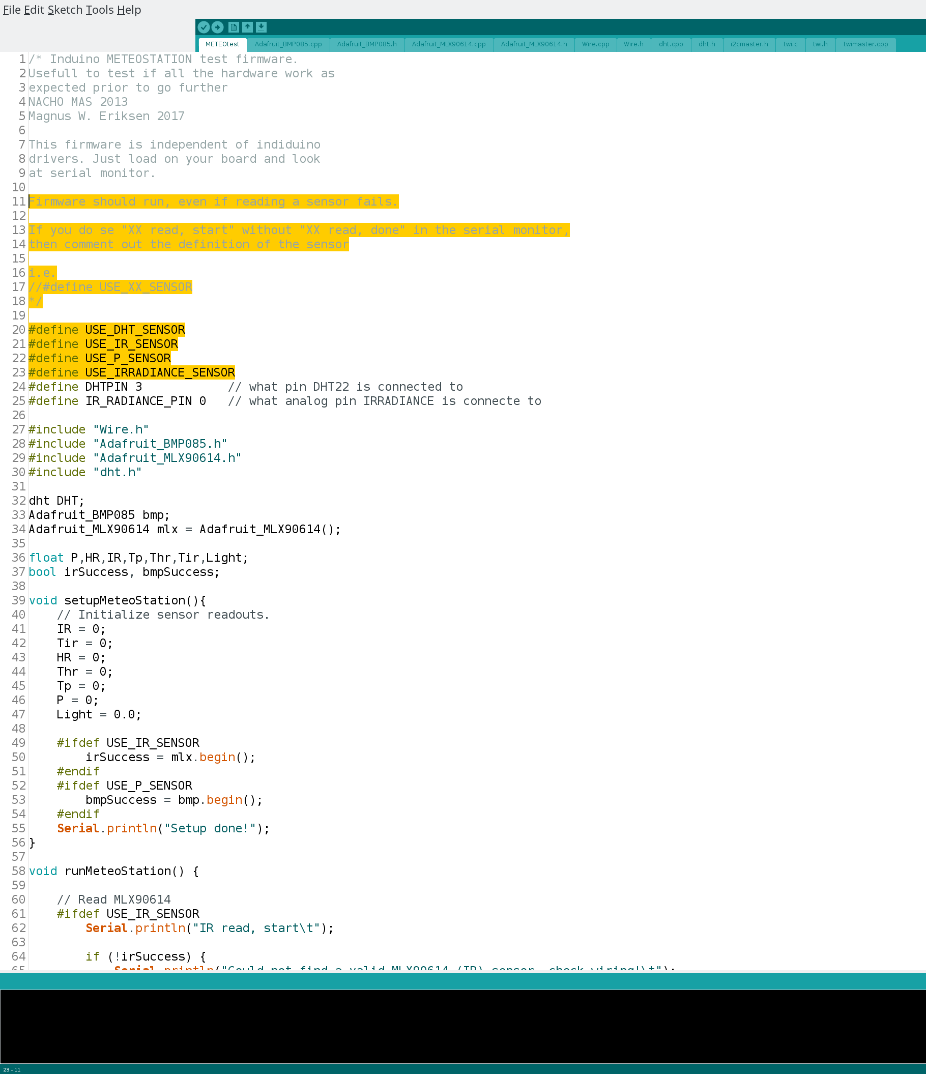
If you are not using the default pins, then they can be changed in the firmware.
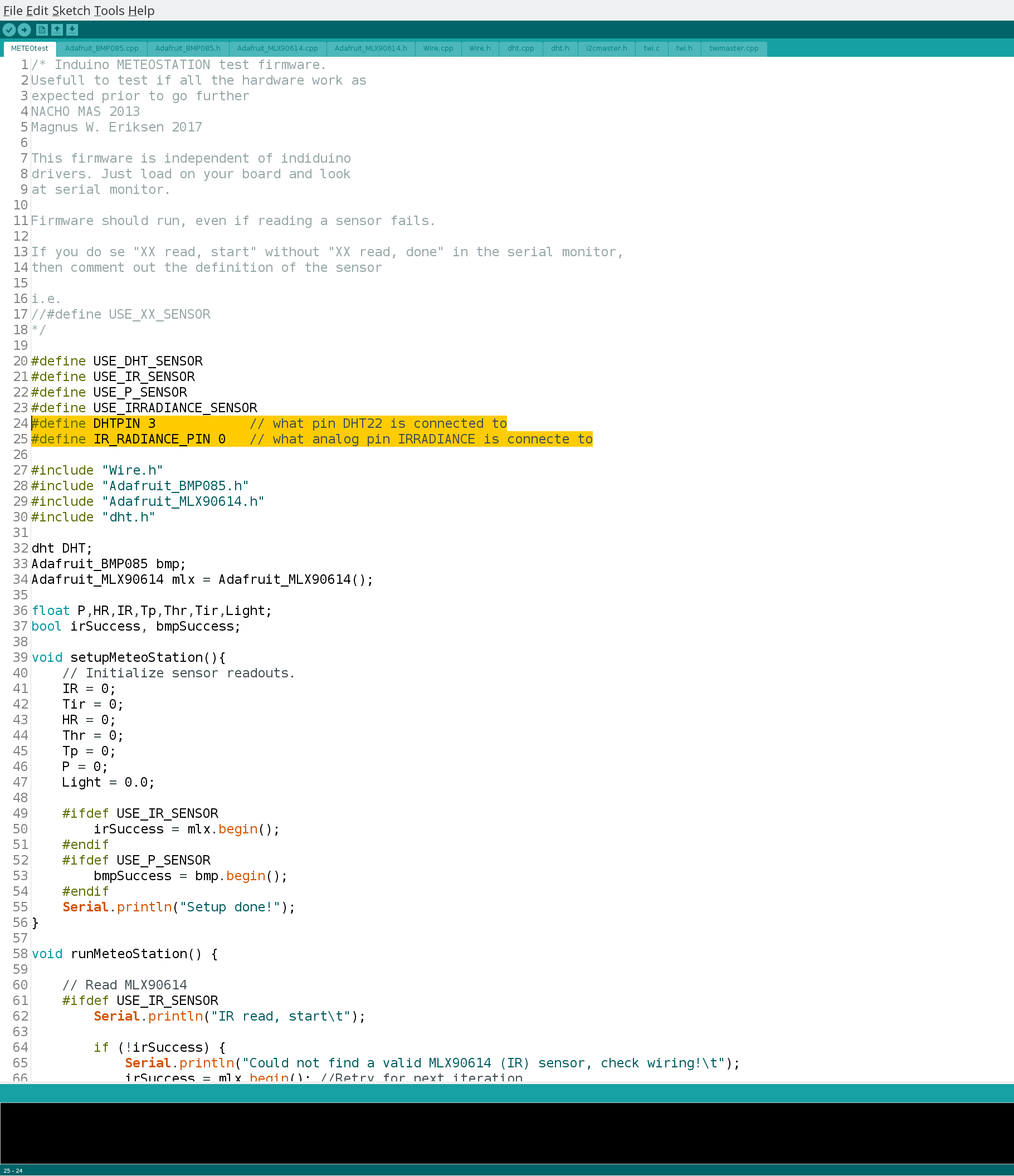
You do not need to edit anything else in the firmware!
5. Configuring, compiling and uploading induinoMETEO
The compiling and upload part of this is the same as for the meteoTEST firmware, but there are more configuration that can be done.
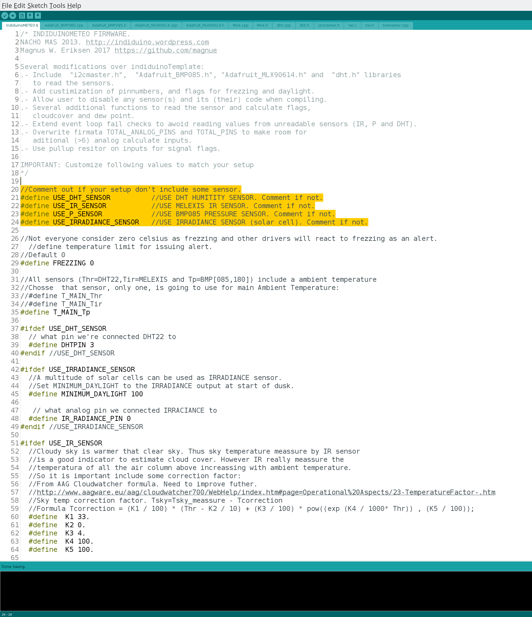
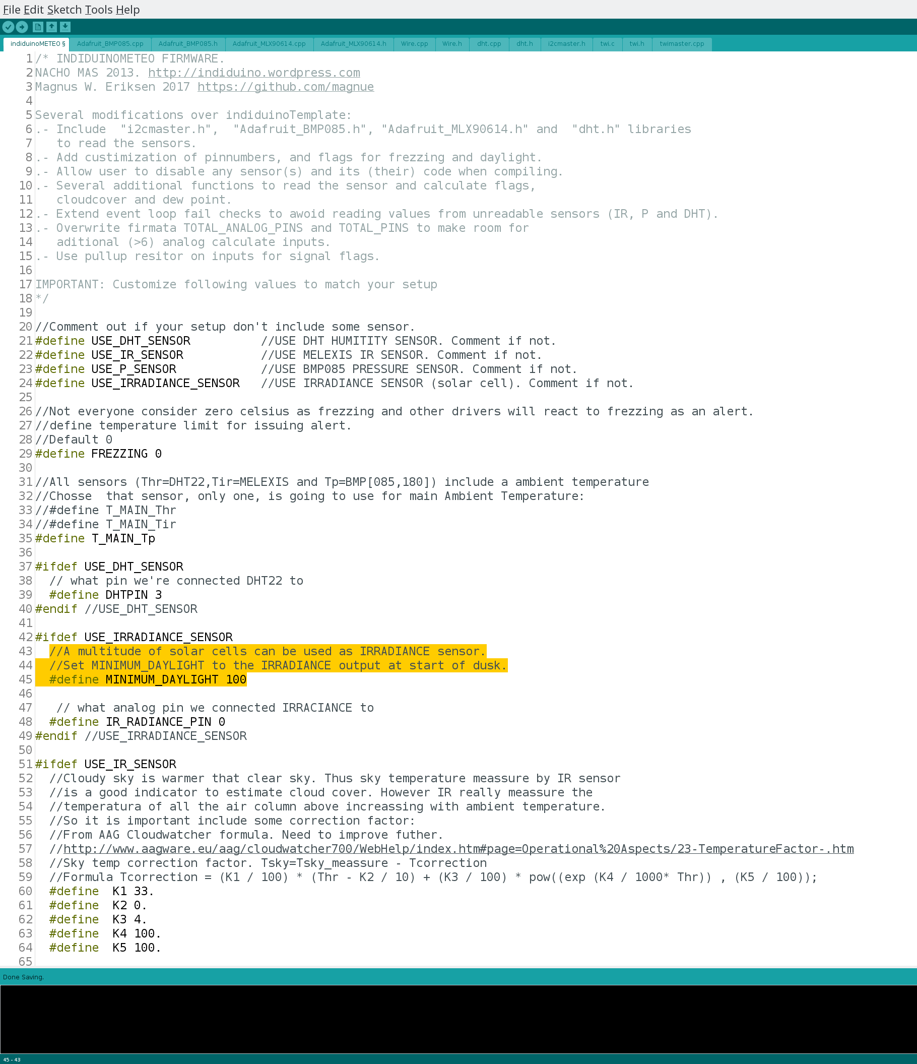
Let’s start off with the sensors used. I do recomend that if you are for some reason not using a sensor, then comment out the definition of it.
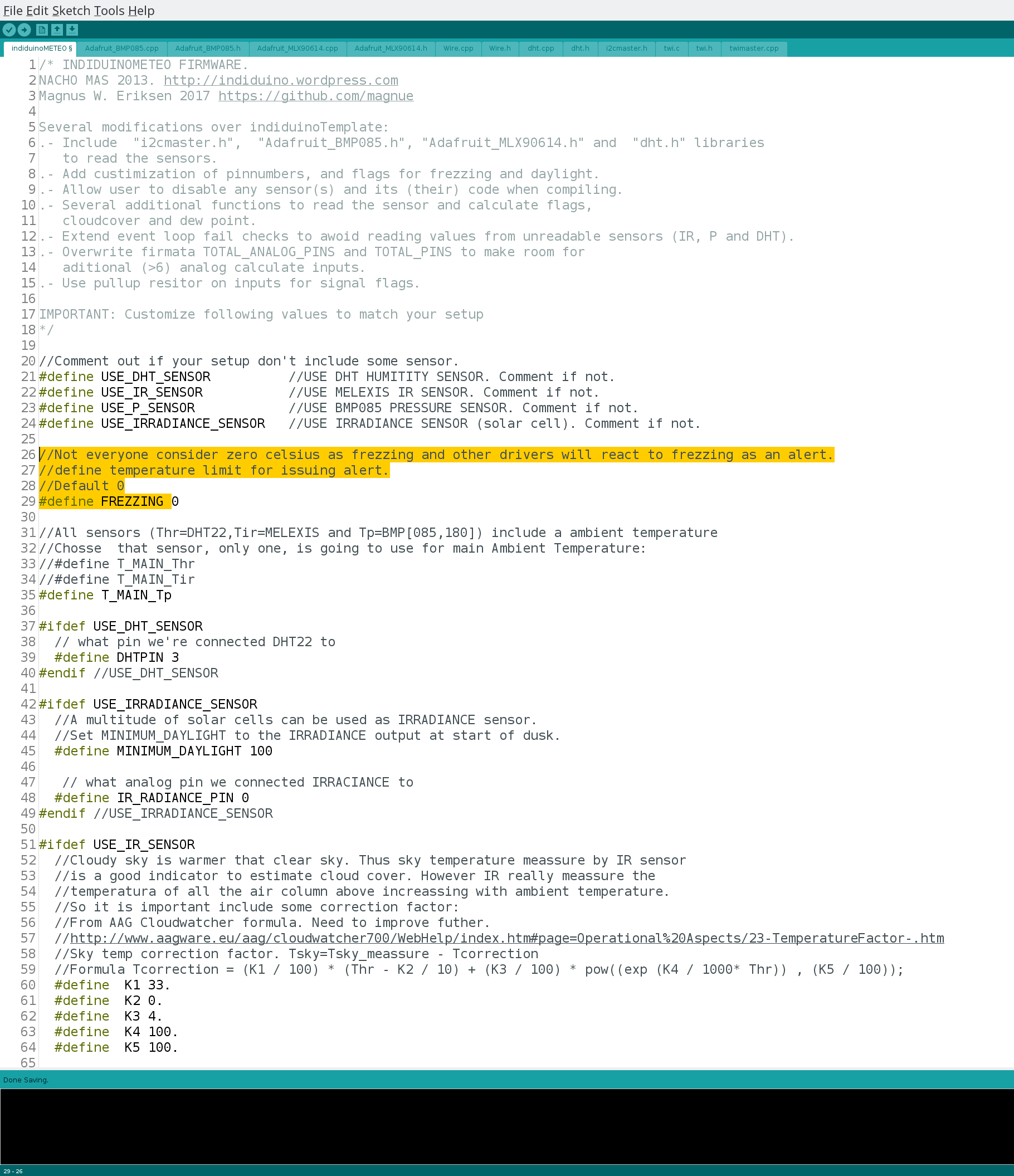
Below 0 celcius is of cource considered frezzing, but you can change it.
I’m imaging in Norway and most of the time during winter, the temperatures will be below 0 degrees. When the firmware detects temperatures below the set value, then the frezzing pin will be set to true. As this is an alert in the indi_duino meteo driver, then clients will react to unsafe eather conditions. I will set mine to -10, but you know best what you need.
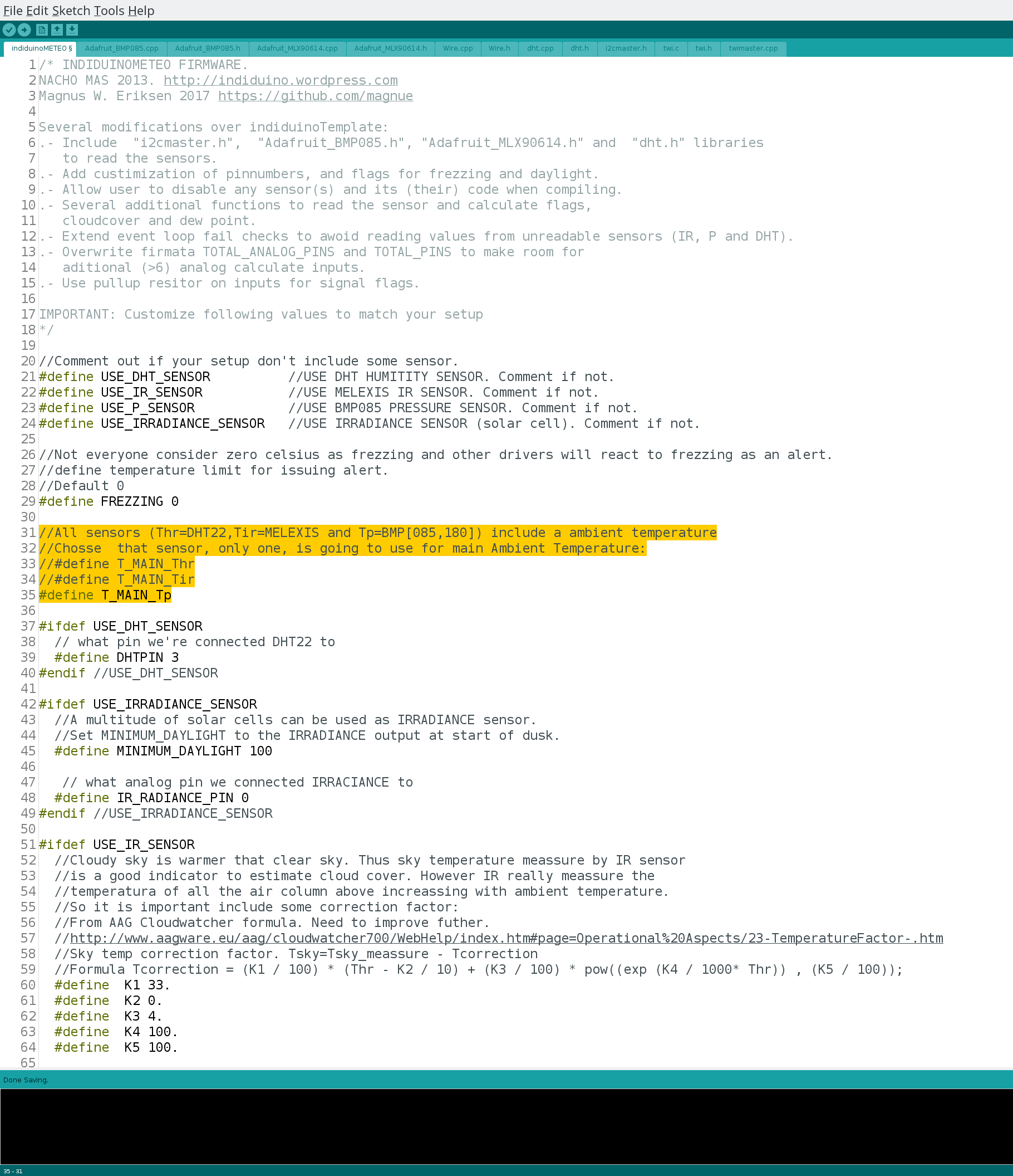
Next is to select witch sensor we should use for ambient temperature. In my installation i found that the BMP 180 gave the best result. You should in most cases be good by leaving this as it is.
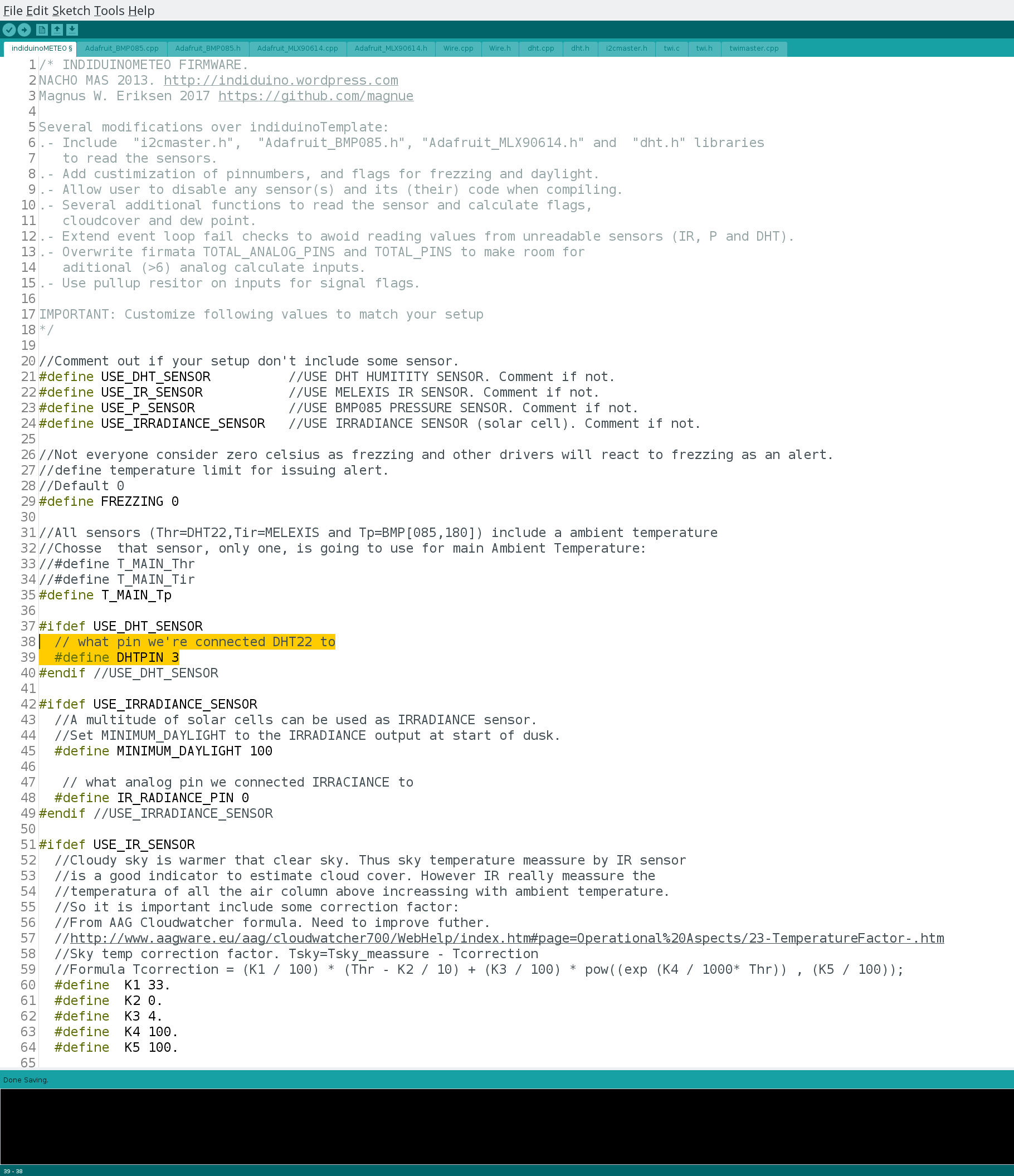
Using a different pin for DHT22? Then update here.
As there are many options of small and low power colar cells, then it is not possible to know what reading yours will have when the sun is setting. To get the correct value for this, then simply check the readout of the irradiance sensor, just after the sun sets under the horizon. This will give you a Daytime alert in the meteo driver, so you know not to open your observatory roof (and or dustcap).
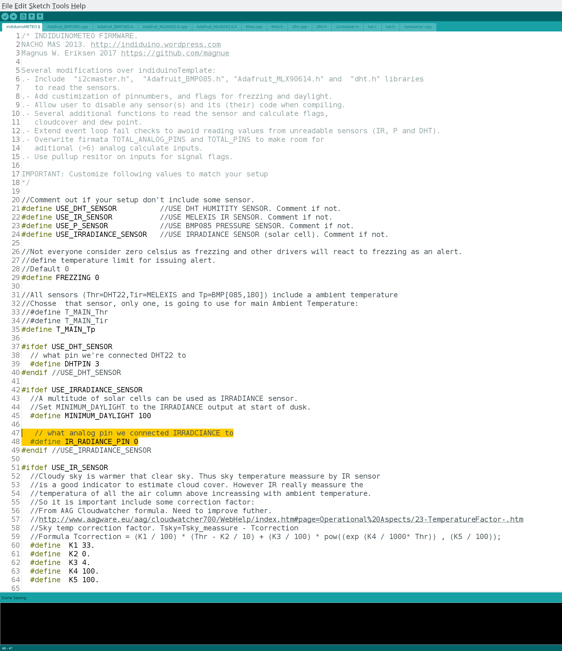
Using a different pin for Ir radiance? Update accordingly.
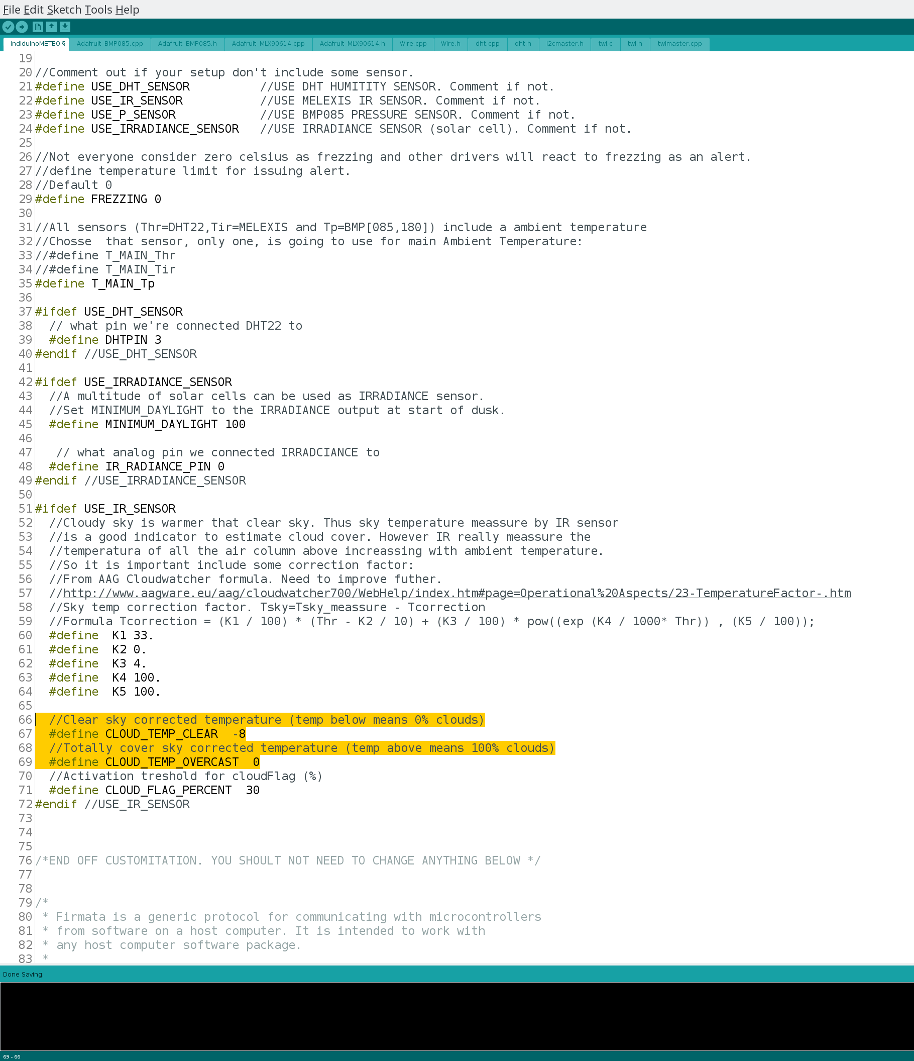
If you are either reading a cloud cover when there are no clouds visible to the sensor, or you have a full overcast with the sensor reporting less than 100% clods, then you can edit this.
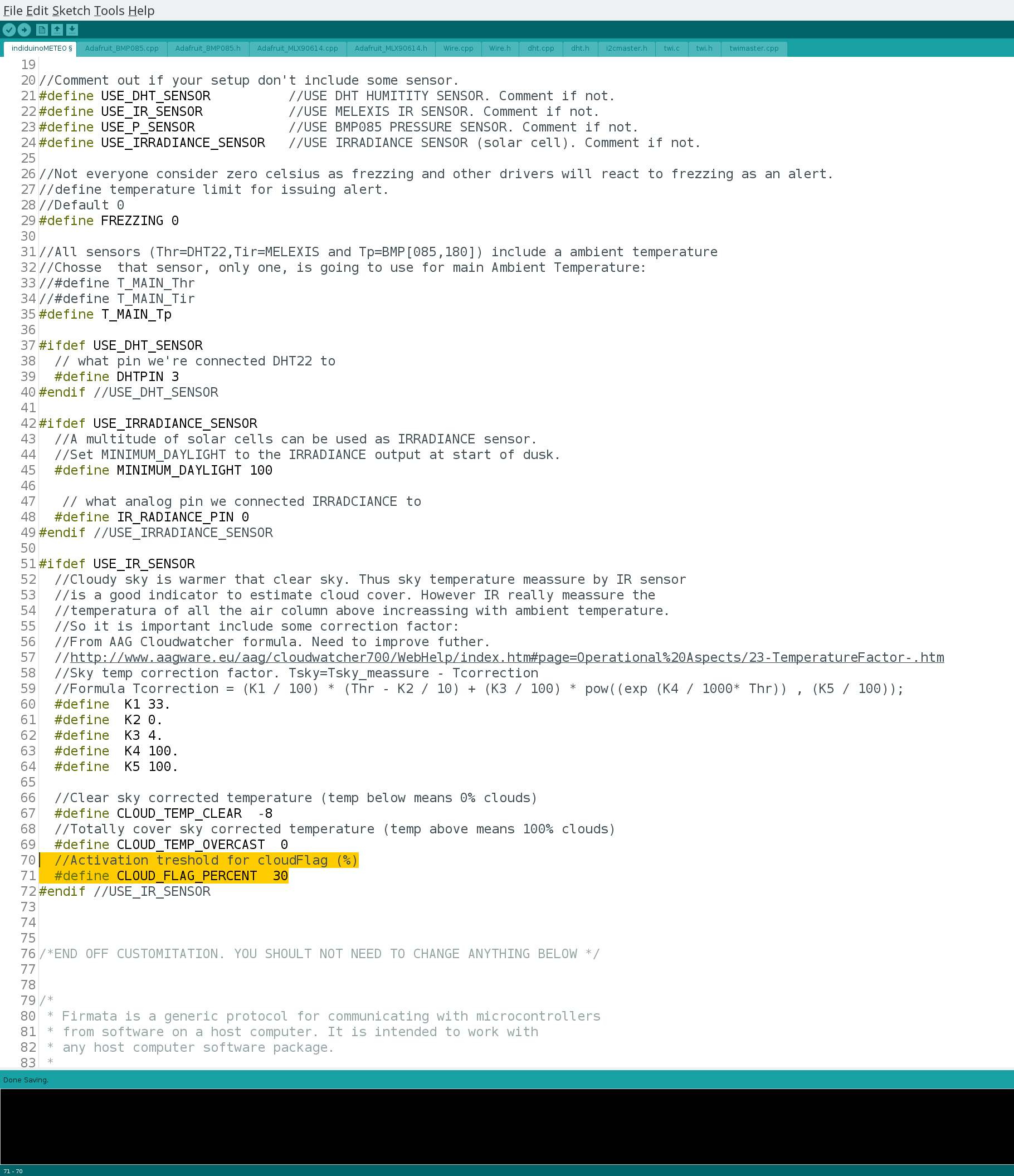
Depending on your use, you might want a clouded warning when it’s more than 15% clods, or you might be happy with less than 50%? Edit this value to customize the alert (cloud flag).
6. Connecting induinoMeteo to KStars with indi_duino driver
You can start the driver locally as any other driver trough Ekos by selecting ‘Arduino MeteoStation’
If you want to start the driver on localhost you will need to create a FIFO file and select the correct skeleton file.
This oneliner should get you started.
killall indiserver; rm /tmp/INDIFIFO; mkfifo /tmp/INDIFIFO; indiserver -f /tmp/INDIFIFO & echo start indi_duino -n \"MeteoStation\" -s \"/usr/local/share/indi/meteostation_sk.xml\" >/tmp/INDIFIFO
It first stops indiserver. Removes any old FIFO file. Creates a new one. Starts indiserver with the FIFO file and the indi_duino driver as MeteoStation with meteostation_ks.xml skeleton file.
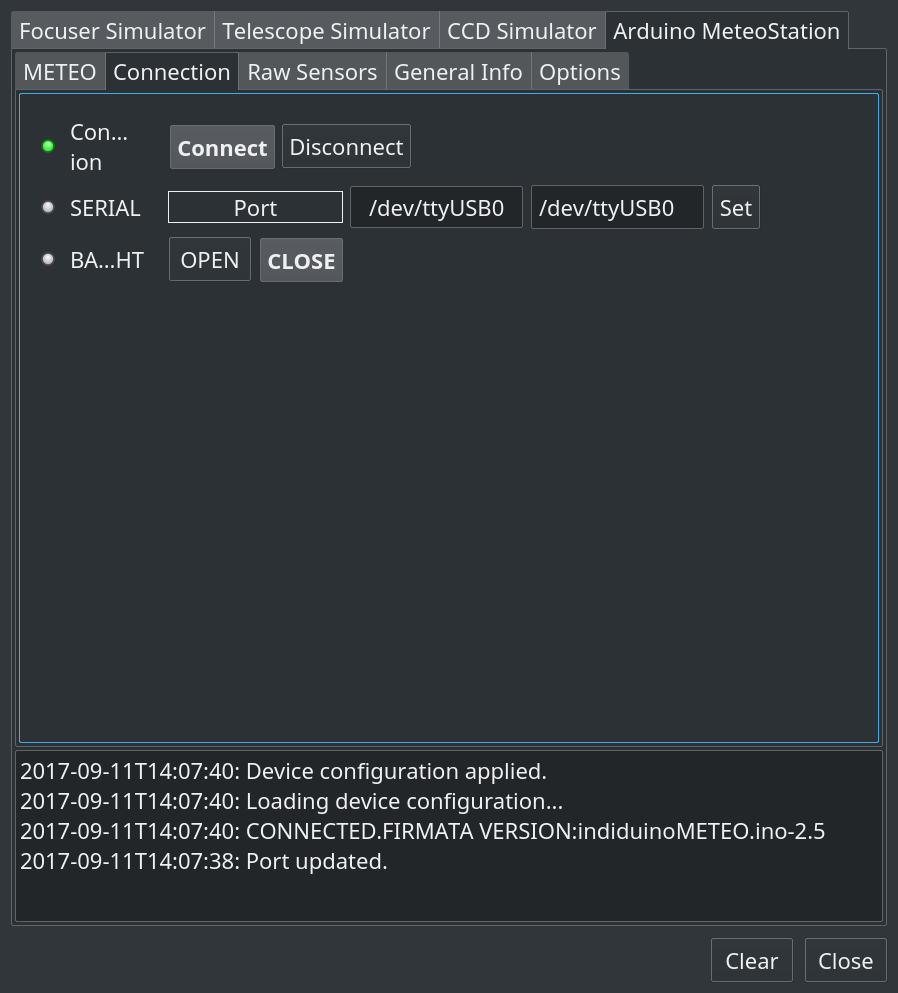
After starting select the correct port in ‘Connection’ tab.
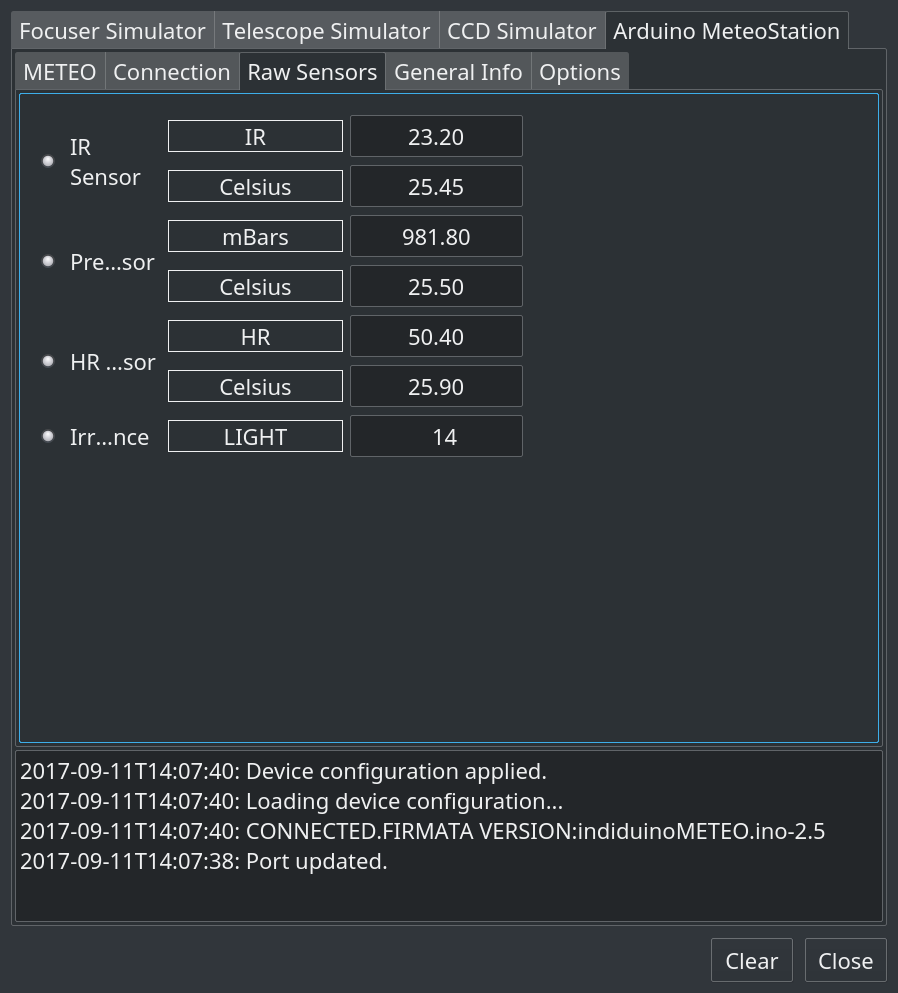
Double check that all sensors report a value in the ‘Raw Sensors’ tab, and the METEO tab should show you the current weather state.
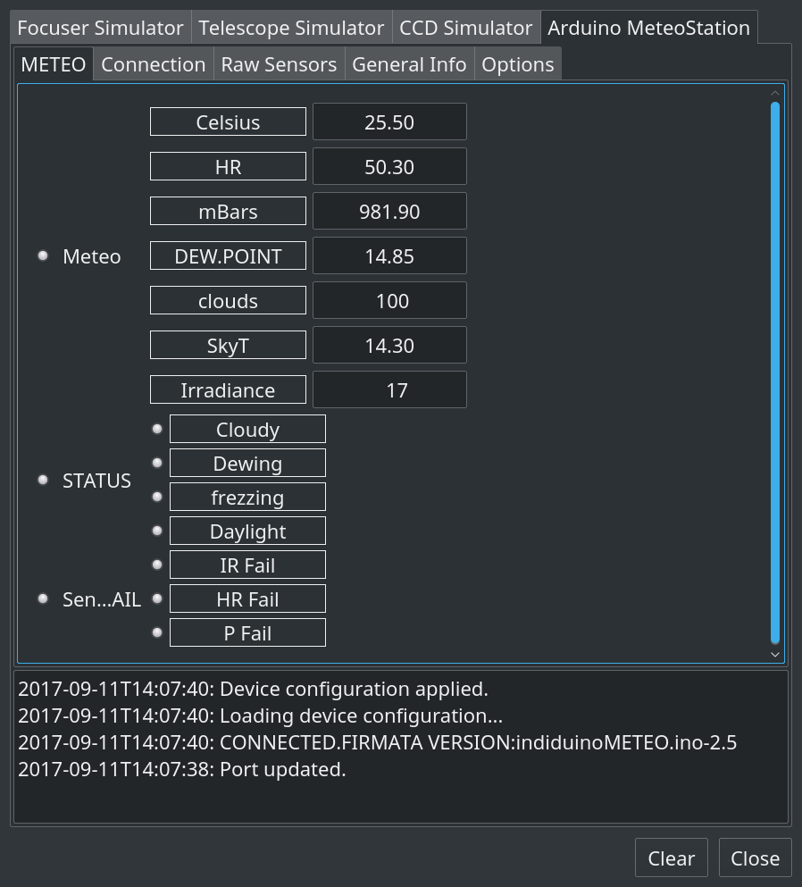
If you have fields in the METEO tab without any data, and you have confirmed that meteoTEST is working, then considure this.
The numerical data sendt from the arduino to the indi_duino driver uses some ‘virual’ analog pins.
Analog pins in arduino has a name pin A0 to An, and these could be mapped differently on your arduino if you are not using a Trinket Pro.
Change the pinnumbers in /usr/local/share/indi/meteostation_sk.xml for numeriacl values, to match your pinmapping.
7. Connecting meteostationWEB to induinoMETEO, and serving trough Apache
This section assumes you have the basic Apache installation up.
Here are some Apache2 basics on help.ubuntu HTTPD - Apache2
You do not need any ssl, as there is no login on the meteostationWEB page.
I will also assume that you are on a distro with python installed.
To get meteostationWEB up from here, then.
7.1. Install dependencies
sudo apt-get install python-rrdtool python-simplejson python-utidylib
7.2. Copy the meteostationWEB folder to your home directory.
cp -r indi/3rdparty/indi-duino/add-on/meteostationWEB ~/
7.3. Create CHART folder and set permission
mkdir ~/meteostationWEB/html/CHART
chmod 775 ~/meteostationWEB/html/CHART
7.4. Create symlink to html directory.
This assumes default apache root directory = /var/www, it could also be /var/www/html
# Do not use ~/meteostationWEB or $HOME/meteostationWEB the symlink needs fullpath
sudo ln -s /home/you/meteostationWEB/html /var/www/meteo
sudo chown -R [you]:www-data ~/meteostationWEB/html
7.5. Reload apache
sudo systemctl reload apache2.service
You should now edit the file ~/meteostationWEB/meteoconfig.py and set your defaults and indi connection options.
7.6. Connection
For connecting to, and starting indiserver on localhost, there are no need to change connection settings.
#1). Local
#by defining INDISERVER as localhost,
#and leaving INDITUNNEL="false",
#then indiserver will be started locally on port INDIPORT
INDISERVER="localhost"
INDITUNNEL="false"
INDISTARTREMOTE="false"
INDIPORT="7624"
To connect to indiserver running on a different host on the same network, then edit #2). Remote, and comment out #1). Local
(You should allways comment out the configs not used).
#2). Remote
#by defining INDISERVER with hostname,
#and leaving INDITUNNEL="false",
#meteostationWEB will connect to indiserver at INDISERVER:INDIPORT
INDISERVER="192.168.10.123"
INDITUNNEL="false"
INDISTARTREMOTE="false"
INDIPORT="7624" # Edit this if indiserver has been started on non default port
To start and connect to indiserver on any remote host, with ssh passwordless keys and up to date indi.
#3). Tunnel with indistartup
#by defining INDISERVER as localhost,
#and setting INDITUNNEL="true" and INDISTARTREMOTE="true",
#then meteostationWEB will open a ssh connection to SSHSERVER:SSHPORT,
#and start indiserver on remote machine on INDIREMOTEPORT,
#and tunnel indiserver to INDISERVER:INDIPORT
INDISERVER="localhost"     # You should not change this
INDITUNNEL="true"
INDIPORT="7624"            # The port that will be used for indiserver on localhost
INDIREMOTEPORT="7624"      # The port indiserver is running on the remote host
INDISTARTREMOTE="true"
SSHSERVER="indiserver.mydomain.com"
SSHPORT="22"
To connect to indiserver running on any other host with, ssh passwordless keys enabled.
Mostly the same settings as #3).
#4). Tunnel with allready started indiserver
#by defining INDISERVER as localhost,
#and setting INDITUNNEL="true" and INDISTARTREMOTE="false",
#then meteostationWEB will open a ssh connection to SSHSERVER:SSHPORT,
#and tunnel indiserver on remote machine running on INDIREMOTEPORT to INDISERVER:INDIPORT
INDISERVER="localhost"
INDITUNNEL="true"
INDIPORT="7624"
INDIREMOTEPORT="7624"
INDISTARTREMOTE="false"
SSHSERVER="indiserver.mydomain.com"
SSHPORT="22"
IN INDI SETTING AND DEBUG you should set what the device port is
##### INDI SETTINGS AND DEBUG #####
#1). Basic indi
INDIDEVICE="MeteoStation"
INDIDEVICEPORT="/dev/ttyUSB0"
And finnaly for connection, you should set the path of your ssh key, and your ssh host username, (if you are using ssh).
##### SSH TUNNEL AN INDI EXEC #####
#Should only need to edit #1), and only if using ssh
#1). Key and user
SSHKEYDIR="~/.ssh/id_rsa"
SSHUSERNAME="magnus_e"
7.7. Defaults
You should atleast set the site related defaults. The RRD Related options is for the Advanced tab, to get expanded weather for your area.
##### SITE RELATED ####
OWNERNAME="Magnus W. Eriksen"
SITENAME="Observatory17b.com"
ALTITUDE=10
#Visit http://weather.uwyo.edu/upperair/sounding.html
#See the sounding location close your site
SOUNDINGSTATION="ENZV"
##### RRD RELATED #####
#PATH TO GRAPHs
CHARTPATH="./html/CHART/"
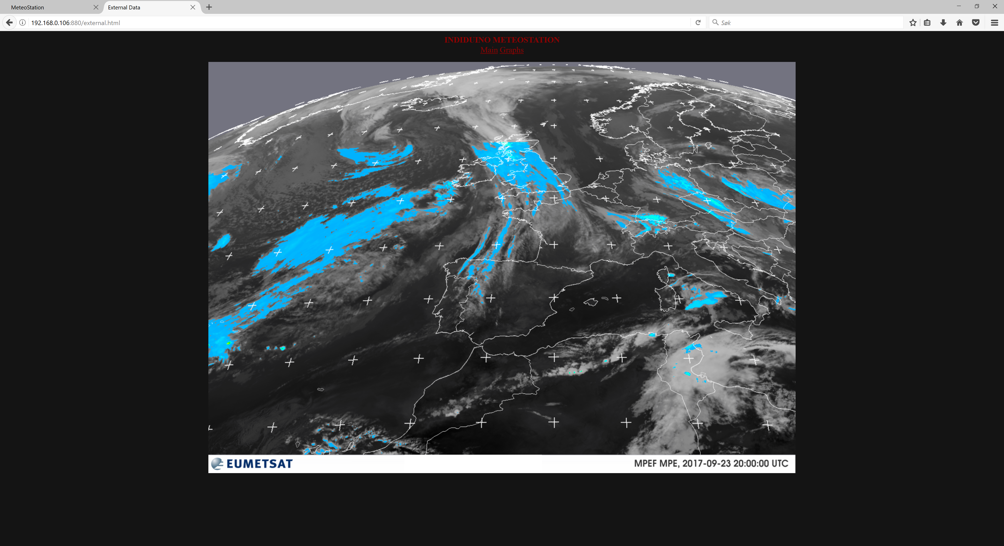
#EUMETSAT lastimagen. Choose one from:
#http://oiswww.eumetsat.org/IPPS/html/latestImages.html
#This is nice but only work at daylight time:
#EUMETSAT_LAST="http://oiswww.eumetsat.org/IPPS/html/latestImages/EUMETSAT_MSG_RGBNatColour_WesternEurope.jpg"
#This show rain
EUMETSAT_LAST="http://oiswww.eumetsat.org/IPPS/html/latestImages/EUMETSAT_MSG_MPE_WesternEurope.png"
#and this cloud cover at IR 39. Work at night
#EUMETSAT_LAST="http://oiswww.eumetsat.org/IPPS/html/latestImages/EUMETSAT_MSG_IR039_WesternEurope.jpg"
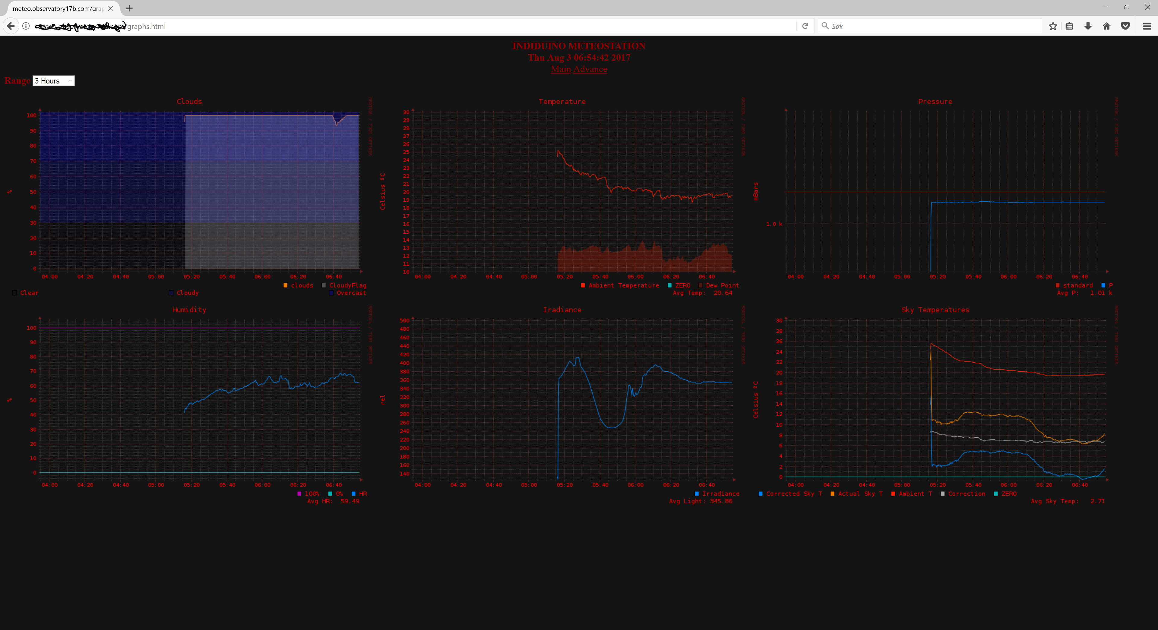
7.8. The meteostationWEB user interface
The index shows the current METEO status.
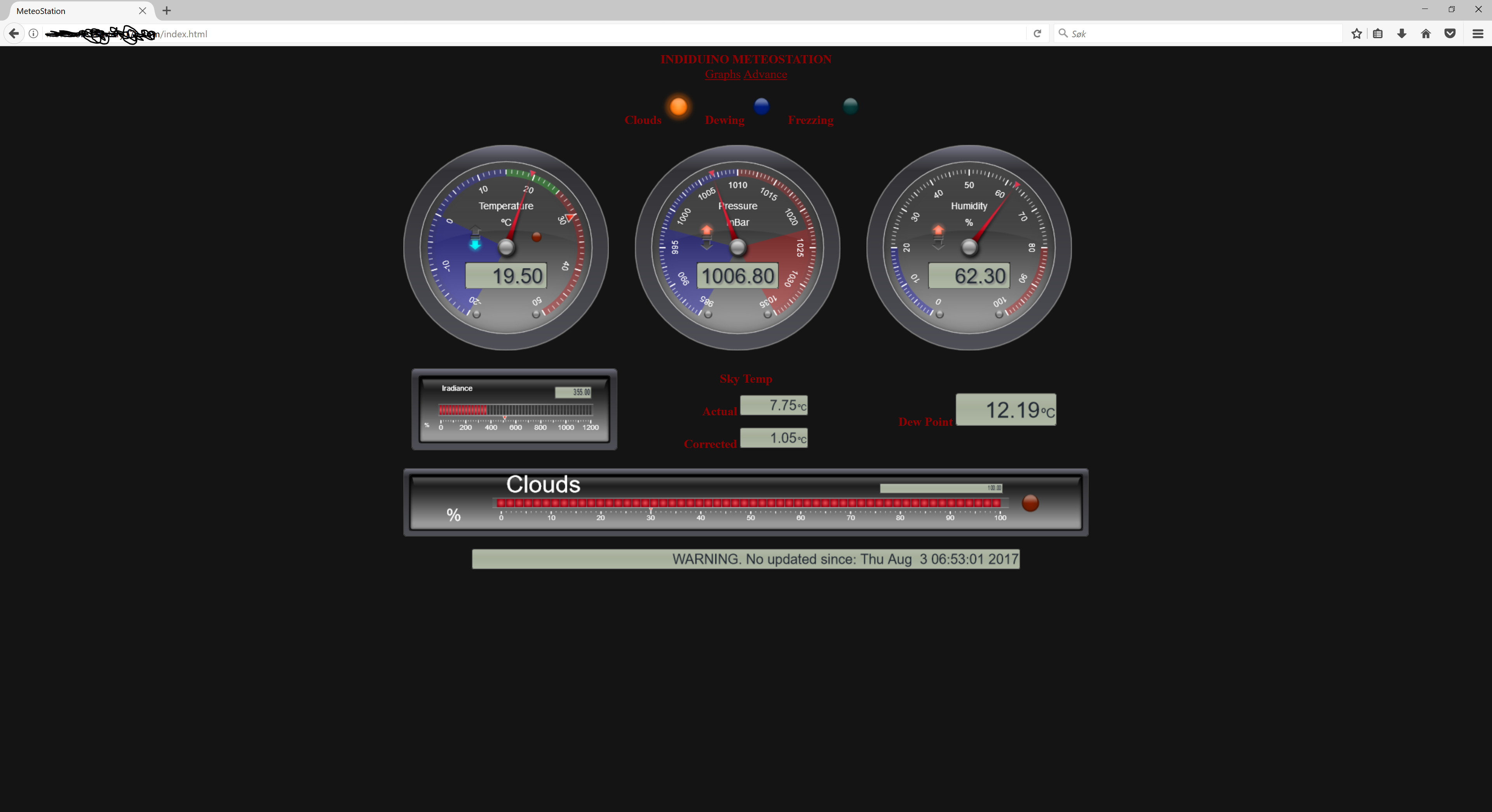
Graps of METEO data, ranging from 3 hours to 1 month back.
EU MET SAT images for your sounding station
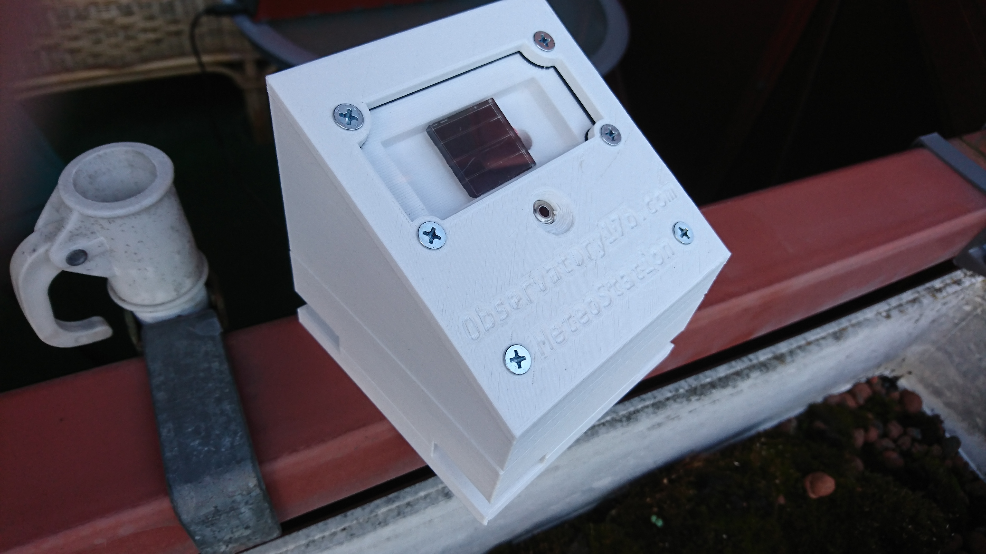
8. Printing and assembling the MeteoStation printable hardware
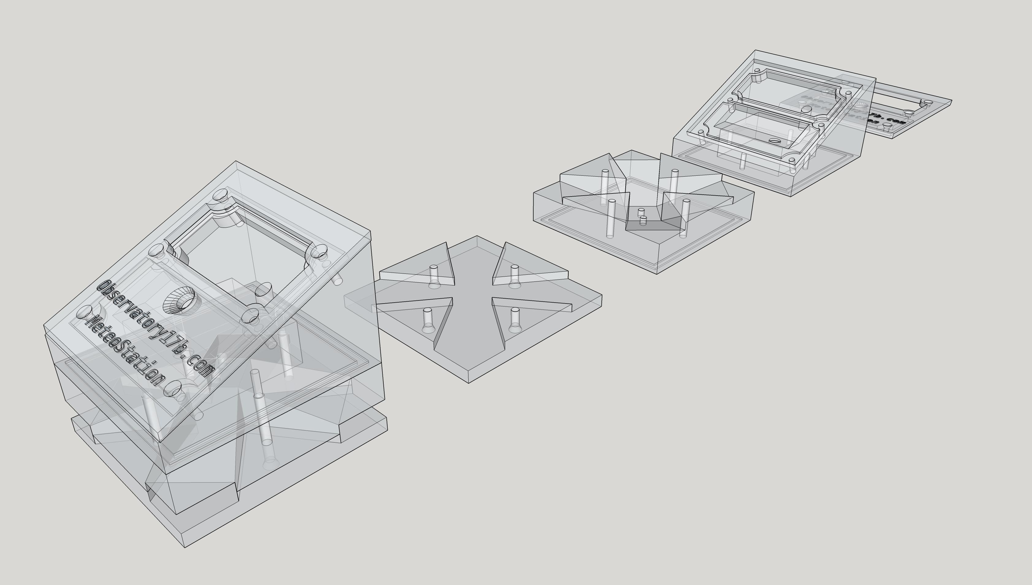
Download the 3d printable MeteoStation on thingiverse hints on prnt settings is in the thingiverse project. Adjust for your printer / filament
If you do not have a 3d printer, you can get the parts printet trough a service like 3D Hubs.
Sumirizing the build steps.
- You need approximately 125m of PETG, 2.65m of TPU and 1.25m of PLA to print this housing.
- Where there are several versions for one part, allways print the one with highest version number.
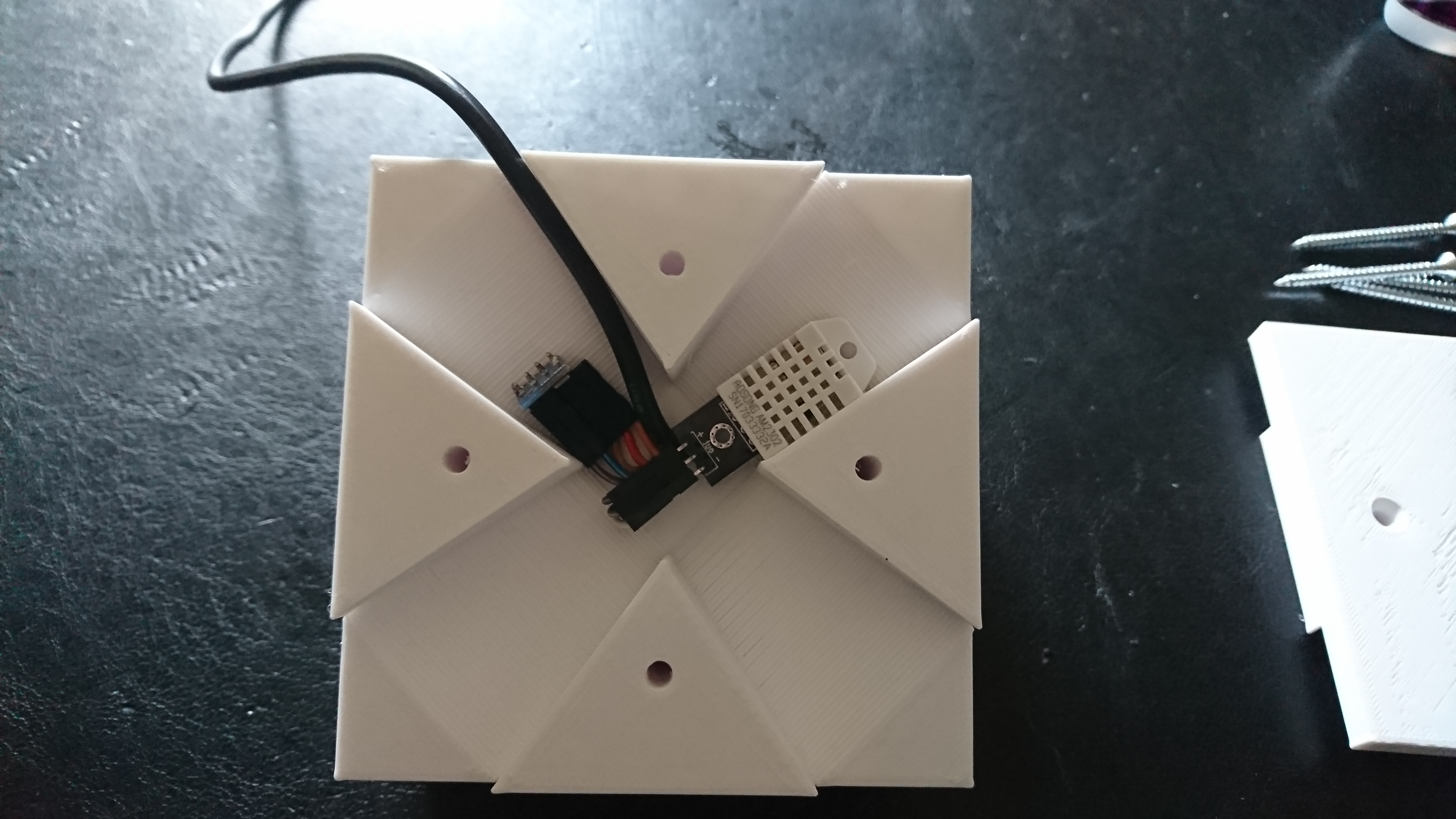
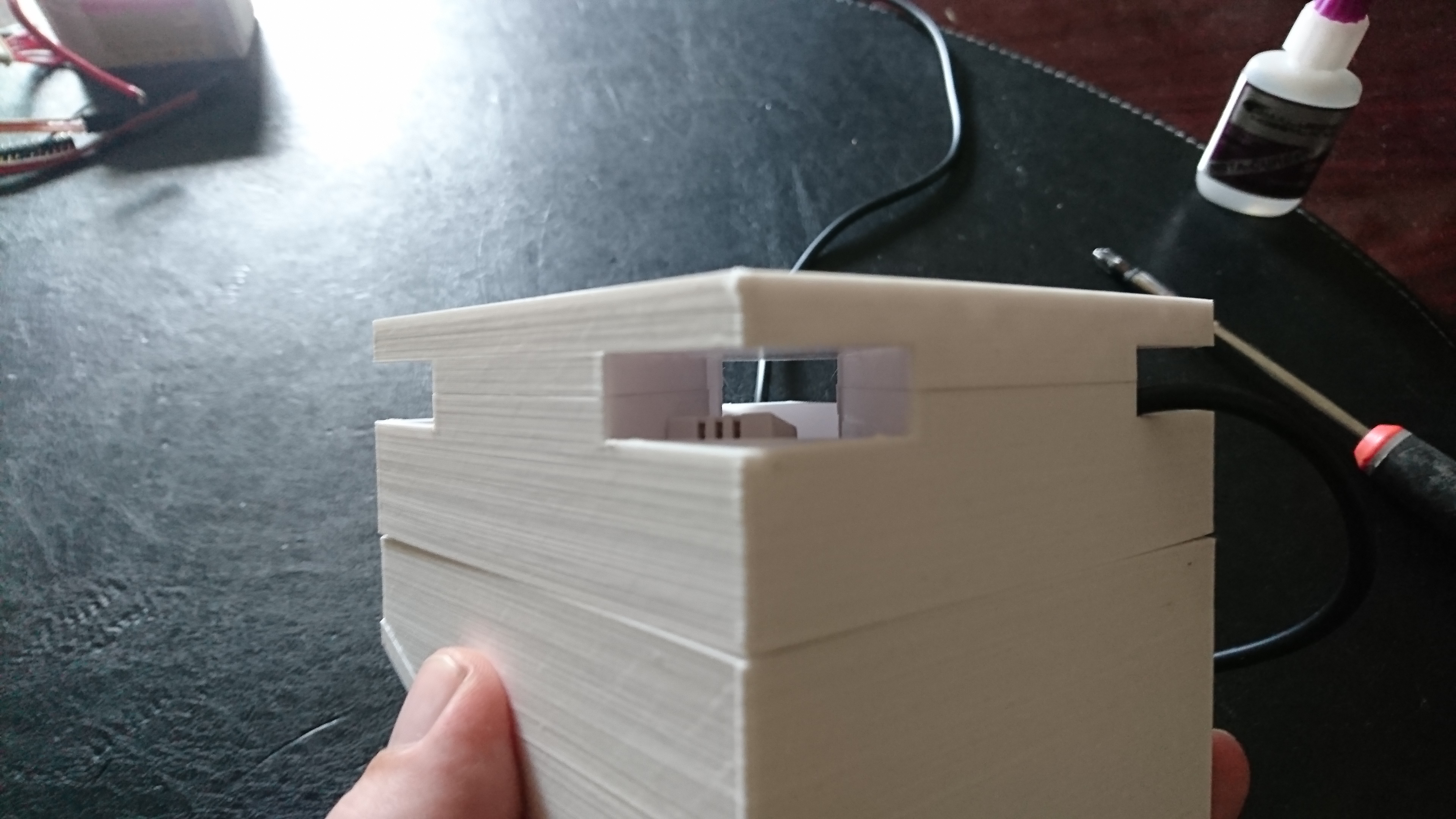
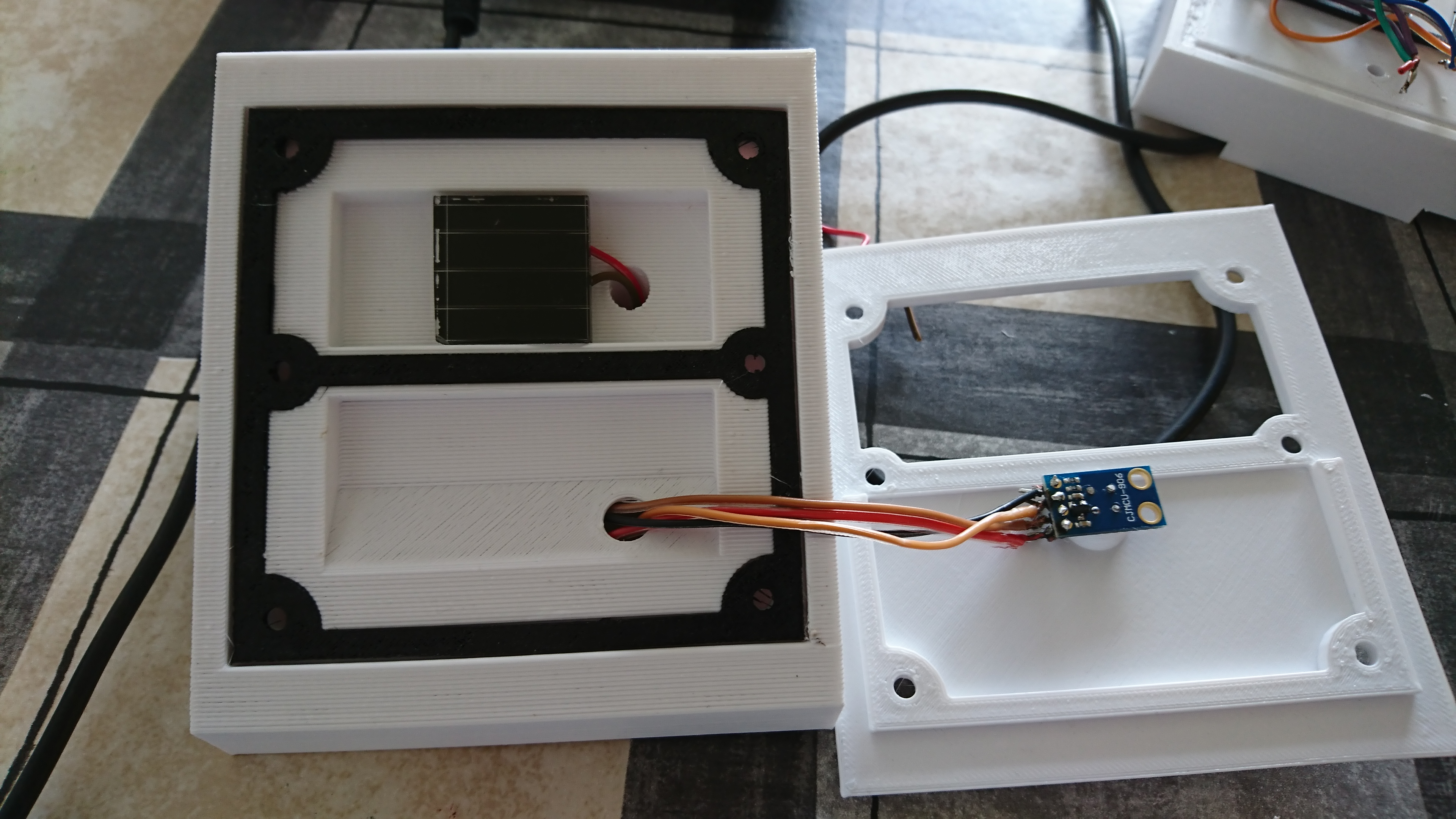
- Use pictures as assembly guide. (More pictures on thingiverse)
- Sensors for temperature and humidity goes in the ‘wind tunnel’ betwean the bottom and middle part.
- IR Radiance sensor mounts under the acryllic glass, and the IR sensor in the opening of the top part.
- You need 2mm thick 9x5 cm acryllic perspex glass, that can be worked on with wood tools.
- Use the part MeteoStation-windowTemplate printed in PLA as a guide to cut the glass to size, and cut holes.
Screws used are all countersunk, and here is 4x 4x50mm + 6x 4x15mm
Finished product is close to 10 cm^3
9. Links to sensors, printable hardware and resources
- Adafruit
- 3d prinatble box
- 3d printing filament
- 3d printing service
- Banggood sensors + misc
- Recources