INDI Library v2.0.7 is Released (01 Apr 2024)
Bi-monthly release with minor bug fixes and improvements
INDI focuser driver for Waveshare Stepper Motor HAT for Raspberry Pi / Rock Pi
- Jeff Wilson
-

- Offline
- Senior Member
-

- Posts: 51
- Thank you received: 12
Replied by Jeff Wilson on topic INDI focuser driver for Waveshare Stepper Motor HAT for Raspberry Pi
Please Log in or Create an account to join the conversation.
- Jose Corazon
-
- Offline
- Supernova Explorer
-

- Posts: 1119
- Thank you received: 182
Replied by Jose Corazon on topic INDI focuser driver for Waveshare Stepper Motor HAT for Raspberry Pi
Hi Eric:
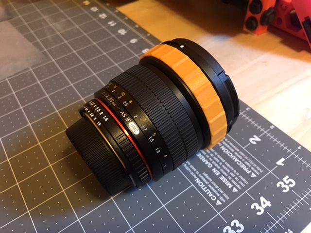
If you have access to a 3D printer, here is a link to the STL files for the geared focuser I designed for my WhiteCat (identical in construction to your RedCat, just a different color - and $30 cheaper when I bought it..
") ). See previous page in the same thread here.
). See previous page in the same thread here.www.dropbox.com/sh/urepva7jg2eq15a/AADkq...DnhqS9KyQW1ZTva?dl=0
The only file not in there is the motor mounting block, which I had designed for an analog motor driven by FCUSB, so you would have to rig one yourself, but that is probably the simplest part to design and fit onto the included rail. Once I have a litte more time again, I will design one and put the file into the same folder. If you beat me to it, it would be great if you would share the stl file as well.
I would suggest going with the clamped design for several reasons: Very easy to put on and take off, much higher tolerance, doesn't have to fit snug off the bat, since you use a screw and nut to tighten it, and it won't slip at all on the rubber ring of the telescope, so no contribution to backlash from that end. Also, the focuser doesn't have to travel very far. As you have also found out, the RedCat has a very narrow focus range, which is difficult to adjust by hand. For autofocusing the ring has to barely move 5 degrees between the extreme focus positions of the autofocus process, to the unwieldy looking extension on the focus ring I designed is not going to conflict with the base plate or anything else. You definitely do not need a contiguous geared ring around the telescope! You manually adjust the telescope to be roughly in focus, then slip on the ring, tighten it with the screw at the 0 degree position on top, move the motor on the rail to engage the gears tightly and you are set.
Inspired by your discussion here and by Kevin's helpful hints, I thought I might give it a try and adapt the same design to a stepper motor.
I used the Moonlight driver compatible Focuser design that Robert Brown generously put in the public domain:
www.dropbox.com/s/ht01zhe3jor9swp/SolderlessFocuser.pdf?dl=0
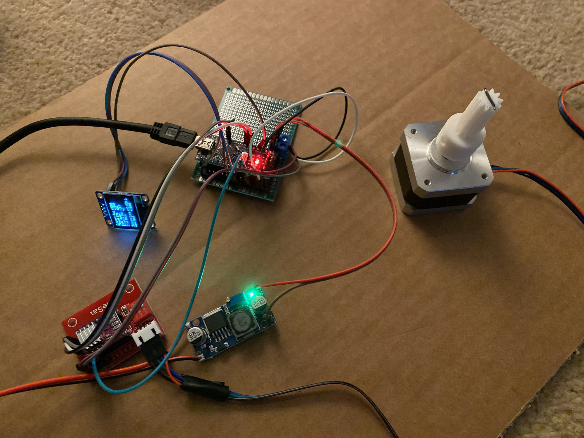
I soldered it together yesterday from a few components. In the image below, I am using a buck converter to step down the 12V input voltage from my standard 12 V power supply to 9 V, mainly because that is what was printed as input voltage on the DRV8825 shield (although the datasheet says any input up to 45V is fine) and because I was not sure whether my cheap Arduino nano clone (($ 3), would take a Vin of 12V or go up in flames trying. Probably, though, the buck converter is not necessary and one can feed the rig directly from the 12V input.
It worked like a charm once I set the current limit on the DRV8825 shield by adjusting the Vref as described here:
www.makerguides.com/drv8825-stepper-moto...er-arduino-tutorial/
For the moment I have the Vref set at 0.33 V, so a max current limit of ~660 mA, but I will see if I can go even lower without affecting motor functionality. If I am losing steps, I can go up to 0.5V, i.e. 1A current limit. I tried that and that also works. Trade-off is that the motor produces more heat, which I obviously want to keep as low as possible, since it is connected to thermoplastic 3D printed gears. You DEFINITELY have to adjust the max current limit! I forgot that and the motor would hum and shake and get extremely hot. I was lucky that it did not fry the stepper driver on the shield. Fortunately, that had overcurrent protection. When I checked, the max current limit was set at 3.2 A, with the motor rated at 1.4A. I almost burned my fingers just touching it.
But once I had adjusted the max current limit, it immediately worked great with the Moonlight Driver in Indi right out of the box, no further modifications required. You can add an OLED, Temperature probe and In/Out LEDs by just uncommenting the respective lines in the header of the code. I used the Focuserv176_DRV8825_HW203_OLED.ino file contained in the zipped firmware folder: sourceforge.net/projects/arduinofocuscon.../ARDUINO%20FIRMWARE/
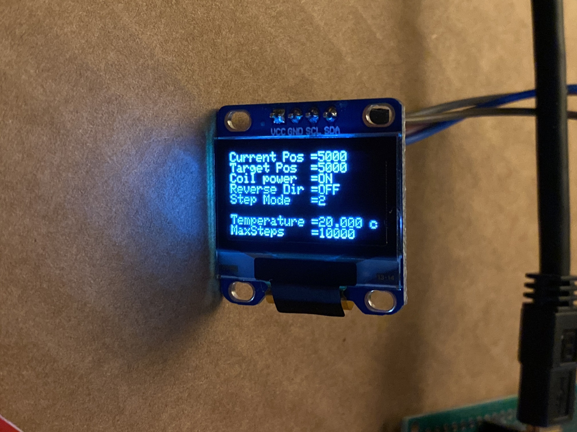
The OLED is inexpensive and it gives you more detailed information about the state of your focuser than simple LEDs:
Here a link to a movie of the set-up which obviously still is a prototype, i.e. I need to build a box around it. But it works!
www.dropbox.com/s/7pwzxom3mpi0z1m/Arduin...serInAction.m4v?dl=0
I used it with a very basic NEMA17 motor (~$6 from Amazon) and microstepping all the way to 6400 step/revolution, fully adjustable from 200 step/revolution in 2x increments all the way to 1/32, i.e. 6400 steps/revolution. That equates to 0.05 degrees/step, which is way more than necessary, given the mechanical tolerances of the gears.
In the movie I only demonstrate 1/32, 1/16 and 1/1 ratios. I think the optimal ratio for use with the geared focus design and Hy's linear focuser is probably going to be 1/16 or 1/32, mainly because I don't want the focuser to move at too high a speed on those gears.
I fully expect that to work on my geared focuser design (see picture above earlier in the thread), since all I really have to do is replace the analog motor with the stepper motor.
I would be interested to hear whether you are using the geared design and how it works for you. Please send me a PM when you do or if you have questions.
Best of luck!
Jo
PS: One more thing: The motor wire connections did not match the pin order on the DRV8825 shield, so I had to cut the wires and connect them in the right order. The colors were correct, though, with Black=1A, Green=1B, Red=2A and Blue=2B.
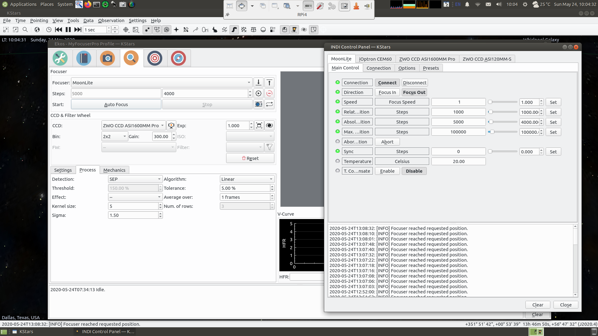
Attached a screenshot of the Control Panel settings and the Focus Module with Linear selected. I highly recommend the linear setup with helical focusers as in the RedCat. Basically eliminates all backlash problems.
Please Log in or Create an account to join the conversation.
- Kevin Ross
-
 Topic Author
- Offline
- Elite Member
-

- Posts: 421
- Thank you received: 102
Replied by Kevin Ross on topic INDI focuser driver for Waveshare Stepper Motor HAT for Raspberry Pi
If you want to be fully Moonlite compatible, just add a DB9 connector for the stepper motor. That's what I did with my setup, since my Waveshare is controlling a Moonlite focuser on one of my scopes (and a DIY solution on another). So I added a DB9 connector to the DIY solution, and now my one focus controller can control both my Moonlite and my DIY setup.
Please Log in or Create an account to join the conversation.
- Kevin Ross
-
Topic Author
- Offline
- Elite Member
-
- Posts: 421
- Thank you received: 102
Replied by Kevin Ross on topic INDI focuser driver for Waveshare Stepper Motor HAT for Raspberry Pi
3D printers also don't use plain old rubber belts. They use timing belts, which are reinforced so they won't stretch.
Please Log in or Create an account to join the conversation.
- Eric Brown
-

- Offline
- Senior Member
-
- Posts: 59
- Thank you received: 3
Replied by Eric Brown on topic INDI focuser driver for Waveshare Stepper Motor HAT for Raspberry Pi
Please Log in or Create an account to join the conversation.
- Jose Corazon
-
- Offline
- Supernova Explorer
-
- Posts: 1119
- Thank you received: 182
Replied by Jose Corazon on topic INDI focuser driver for Waveshare Stepper Motor HAT for Raspberry Pi
Others here in the forum told me that they had similar problems with belts as you did. The problems actually only arise with focusers that need very little travel, like the helical focuser in the RedCat. There, even a minimal stretch of the belt is deleterious. If the belt is driving the fine focus knob on an RC8, for instance, a little backlash is much more forgiving.
I could immediately see that problem, which is why I never implemented the belt driven design on my WhiteCat (despite having all the parts already). Maybe one day I will, just to see how big the difference is.
For your RedCat, as you are writing, there is very little tolerance for backlash, so the belt has to be incredibly tight. That will put a lot of strain on the bearings in the motor, which could cause other problems.
All I can say is, the gears don't have that problem, they work GREAT, and in combination with the Linear focus algorithm there is no backlash problem. Hits perfect focus every time.
If you are up to it, since you already have the belt-driven design implemented, would you mind giving it a try and comparing the two different designs? You obviously have a 3D printer, so printing the STL files I shared will be just one overnight job on the printer (if your platform is big enough to fit them all on there). All you need then is a bracket for the NEMA17. I can help with that, if you want.
Let me know. It will be fun working out the optimal focuser for the RedCat, many people now have that and paving the road towards a simple self-built autofocuser would be beneficial to a lot of people reading this forum, I presume.
Best wishes and clear skies,
Jo
Please Log in or Create an account to join the conversation.
- Eric Brown
-
- Offline
- Senior Member
-
- Posts: 59
- Thank you received: 3
Replied by Eric Brown on topic INDI focuser driver for Waveshare Stepper Motor HAT for Raspberry Pi
Ultimately it does seem like a geared approach is generally better though. One of my goals was to allow the RedCat to be completely retracted when not in use. Given that it needs nearly 180° of rotation to do that, I'd need to mount the stepper above the scope or add a riser of some sort to allow room for the gears underneath the scope. I'll have to do some calculations to see if there might be enough clearance for an appropriately-sized gear between the scope and the dovetail if my mounting base wasn't in the way. I might be able to add a slot with clearance for the gear is that seems feasible. How far does your gear extend out from the surface of the focuser?
I still would like to try my geared stepper, though I'm not sure its actually going to work. When testing with the existing driver doing 32-microsteps and having it step just one step, it doesn't always move forward a consistent amount. I'll have to see if the other stepper I have been using does the same thing. I wonder if there is an issue with the stepper driver or the configuration of the Waveshare stepper hat.
Please Log in or Create an account to join the conversation.
- Eric Brown
-
- Offline
- Senior Member
-
- Posts: 59
- Thank you received: 3
Replied by Eric Brown on topic INDI focuser driver for Waveshare Stepper Motor HAT for Raspberry Pi
Please Log in or Create an account to join the conversation.
- Jose Corazon
-
- Offline
- Supernova Explorer
-
- Posts: 1119
- Thank you received: 182
Replied by Jose Corazon on topic INDI focuser driver for Waveshare Stepper Motor HAT for Raspberry Pi
My 2 cents on this is that upon microstepping down to 1/32 and using only one step for each move, the motor does not have enough torque to reliably move that one microstep.
That will be very difficult to fix, except for replacing the motor with a much heavier NEMA 23 or even NEMA27, or putting an elaborate transmission in place to reduce the motor torque, or by replacing the NEMA17 with a geared motor (which you are planning to do, using an 18:1 gear ration, I presume).
It really comes down to the problem that the helical focuser on the RedCat has A LOT of internal resistance, especially going out, and that the focal plane is very narrow. Also, the angular movements of the helical focuser have to be exquisitely small, given the narrow focal plane of the lens.
I doubt a belt-driven focuser can achieve that consistently. Even deepskydad says that their focuser needs to be moved out 5 mm at least, lest there is too much friction on the tube (I can confirm the friction part).
As for the STL files: I made the designs using FreeCAD, not Fusion360, happy to share those as well, but the STL files should be translatable immediately without further modifications.
The only thing you would have to forego moving the tube all the way back at the end of the night. Not necessary, IMO. But you can always do that manually, if you are worried about the tube sticking out 10 mm or so.
Hope that helps.
Jo
Please Log in or Create an account to join the conversation.
- Jose Corazon
-
- Offline
- Supernova Explorer
-
- Posts: 1119
- Thank you received: 182
Replied by Jose Corazon on topic INDI focuser driver for Waveshare Stepper Motor HAT for Raspberry Pi
Direct drive, no gears on the motor. Gear ratio is approximately 1:2, due to moving out the secondary gear segment with the extended arm of the gear ring clamped to the helical focusing ring of the telescope.
Please Log in or Create an account to join the conversation.
- Kevin Ross
-
Topic Author
- Offline
- Elite Member
-
- Posts: 421
- Thank you received: 102
Replied by Kevin Ross on topic INDI focuser driver for Waveshare Stepper Motor HAT for Raspberry Pi
When using the Waveshare INDI driver that I wrote, a single step in the INDI control panel will equate to 32 microsteps at the motor. I always end on a full step boundary. I use microsteps for smoothness and quietness, not for increased resolution. If it were to stop on less than a full step, then the motor would need to have power applied to it constantly to hold that position, thus using more power and causing the motor to get warm (or very hot if you haven't tuned the current limit). But with my approach, that allows me to turn off power to the motor when not actively moving for focus.
So I'm not sure if that is esb's problem of it not always moving the same amount with a single step. Does that also happen if you disconnect the belt, just letting the motor run free? If it works fine when the motor is running free, but misses a step when connected to the belt, then it is most likely a lack of torque. You can try slowing down the motor with the delay settings, since stepper motors lose torque when running faster. You can also try using less microstepping via the DIP switches. You will need to modify the source code to match the micrstepping setting of the DIP switches. Eventually I'll make that a configurable option in the INDI control panel.
Please Log in or Create an account to join the conversation.
- Eric Brown
-
- Offline
- Senior Member
-
- Posts: 59
- Thank you received: 3
Replied by Eric Brown on topic INDI focuser driver for Waveshare Stepper Motor HAT for Raspberry Pi
I did some additional experiments with the geared stepper and discovered that the problems I was seeing with inconsistent (even backwards) movement went away when I increased the step delay in the WMH driver. I had been using a 40us delay per step, and am now using 100us. I'm guessing it was trying to micro step too quickly. I bet that's the issue I was getting on my regular stepper as well. I'll have to see if it performs better with the higher step delay. I also have the option of turning micro stepping off completely. The only reason it was used in the first place was to smooth out the motion and not to actually increase resolution. But if the stepper loses torque in the process, it might be better to just use the native step size of the motor. The gearing should improve both torque and resolution.
I had been looking for your original CAD files to adapt your gear design to my layout. However I can do that pretty readily in Fusion360 if I need to. I also probably have a Nema bracket around somewhere if I end up trying out your design. I'm still hopeful that I can get the belt driven solution to work.
Please Log in or Create an account to join the conversation.